Articles
DC & AC Voltage Measurement
USB-IO Interface Adapter has 5 analog inputs connected to internal 10-bit analog to digital converter. You can use these analog inputs to measure DC and AC voltage.
USB-IO adapter sends the results of the measurement to PC software. The voltage can be measured on demand (when PC software requests to measure voltage on the specified analog input pin) or periodically (each in milliseconds).
You can use either the USB-IO adapter positive and negative supply voltage (VDD and VSS) or the voltage level on the C.6 (VRefHi) and C.5 (VRefLow) pins as analog reference voltage.
For additional information about USB-IO adapter ADC module see our article ADC Module Overview.
DC Voltage Measurement
The analog input voltage of USB-IO adapter analog to digital converter should not exceed 5V.
If the analog input voltage would not exceed the VRefHi (high reference voltage), you can connect your circuit directly to USB-IO adapter analog input pin through current-limiting resistor (1-2k).

If you want to measure voltage in wider range, add an external resistive divider:

The resistors used in this divider should meet the following requirements:
The total input resistance (R1+R2) should be at least 10 times greater than the output impedance of the connected circuit;
The total input resistance (R1 + R2) should be at least 10 times less than the input impedance of the ADC;
The ratio between R1 and R2 should comply with the equation:

where: Vadc is the maximum input voltage of the ADC (5V in our example); Vin is the maximum input voltage of the resistive divider (maximum output voltage of the connected circuit).
Example:
You need to measure the voltage from 0V up to 30V. The output impedance of the connected circuit is 1k. The total resistance of R1 and R2 should be within:

In current example we will set R1+R2 to 300k.
You can calculate the R1 and R2 values with the equation:

AC Voltage Measurement
You can measure the AC voltage by measuring the amplitude of the positive half-wave.
The possible connection to USB-IO adapter is illustrated by the following schematics:

In case of sinusoidal signal, you can get the actual voltage level with the following expression:

where: VIn - measured input voltage; ADC Code - ADC digital code received from USB-IO adapter.
We are currently developing algorithm to measure voltage level of an arbitrary AC signal. If you want to be notified when it is ready, send an e-mail to support@diolan.com.
DC Motor Controller
A DC motor is an electric motor that runs on direct current (DC) electricity.
There are several possibilities to implement a DC motor controller. The rotational speed of the DC motor is proportional to the voltage applied to it. Varying the voltage you can change the motor speed.
The effective voltage (and therefore the DC motor rotational speed) can be varied by inserting a series resistor or by an electronically controlled switching device made of thyristors or transistors. All these approaches require significant changes in schematics and are hardly controlled from software.
Much better way to control the DC motor rotational speed is by using a Pulse Width Modulation (PWM). To understand how PWM can control the DC motor we should introduce the duty cycle term. The duty cycle (D) describes the proportion of positive pulse width (W) to the period (T).
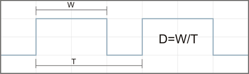
Current only flows through the motor during the "ON" portion of the PWM waveform, so the average voltage applied to the motor is varied by changing the duty cycle. For example, with a 100 V supply and a 30% "ON" time (D=0.3), the average voltage at the motor will be 30 V.
On the following figure you can see the PWM generator circuit for DC motor controller.
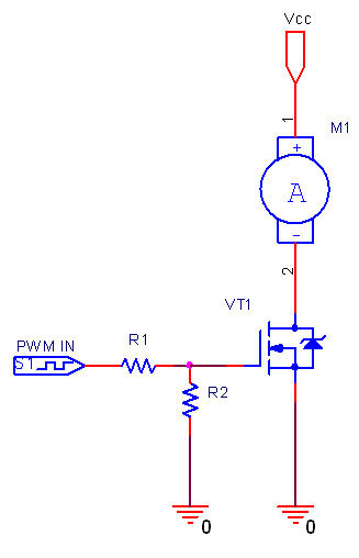
DC motor controller can be implemented using the PWM functionality of DLN-Series USB-IO/I2C/SPI Interface Adapters.
Digital-to-analog converter (DAC)
In electronics, a digital-to-analog converter (DAC or D-to-A) is a device for converting a digital (usually binary) code to an analog signal (current, voltage or electric charge). You can use DAC for testing circuits and amplifiers or for generating the high complexity signals.
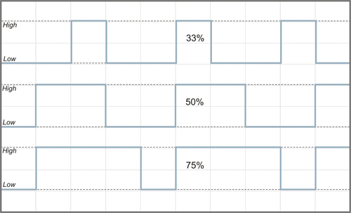
Digital to analog converter can be easily implemented with Pulse Width Modulation (PWM). On the following figure you can see three PWM signals with different duty cycles. The duty cycle describes the proportion of positive pulse width to the period. PWM waveforms with 33%, 50% and 75% of duty cycle are shown below. These three PWM signals can be converted to three different analog values, at 33%, 50%, and 75% of the full strength. For instance, when the voltage level is 5V and the duty cycle is 50%, digital to analog converter outputs 2.5V.
The simplest saving digital to analog converter circuit with high-resistance output is presented on the following schematics:

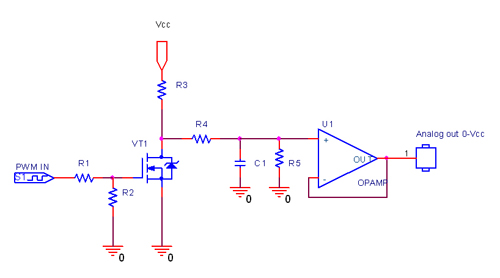
The next figure shows the digital to analog converter circuit with low-resistance output:

To get the DAC with the voltage range different from 5V, you can use the circuit from the following schematics:
Analog Inputs (ADC Module) Overview
Analog Reference Voltage
GPIO-24 analog to digital converter can measure input voltage levels from VRefLow up to VRefHi.
There are 4 modes to setup VRef source of GPIO-24 analog to digital converter:
- VRefHi is positive supply voltage (VDD), VRefLow is negative supply voltage (VSS);
- VRefHi is the voltage level on the C.6 (VDD), VRefLow is negative supply voltage (VSS);
- VRefHi is positive supply voltage (VDD), VRefLow is the voltage level on the C.5;
- VRefHi is the voltage level on the C.6, VRefLow is the voltage level on the C.5.
Following requirements are reasonable for each mode:
- Reference Voltage Range (VRefHi – VRefLow) >= 3V;
- Reference Voltage High VSS<VRefHi<VDD;
- Reference Voltage Low VSS – 0.3V<VRefLow<VDD – 3.0V;
- Recommended Impedance of Analog Voltage Source – 2.5k.
With external reference voltage you can achieve better accuracy of measurement than with USB-IO adapter supply voltage. USB-IO adapter supply voltage depends on the voltage level of USB port. When using the external reference voltage, keep in mind that any analog input voltage must not exceed VRefHi.
An inexpensive way to generate VRef is by employing a zener diode (mode 1 VRefHi is the voltage level on the C.6, VRefLow is negative supply voltage (VSS)):

Most common zener diodes offer 5% accuracy. Reverse bias current may be as low as 10 μA. However, larger currents (1 mA - 20 mA) are recommended for stability, as well as lower impedance of the VRef source.
Finally, various reference voltage generator chips (typically using on-chip band-gap reference) are available. They are more accurate.
You can measure larger range of voltage levels if you connect the analog input to the output of a voltage divider. It theory, you can measure an indefinitely large DC and AC voltage levels with the help of resistive dividers. But keep in mind that GPIO-24 adapter does not have galvanic isolation from the PC. The improper connection to the source of high voltage (or current) can damage both the USB-IO adapter and the PC. We don’t recommend to measure voltage above 40V with this USB-IO adapter.
Association Between Analog Input Voltage & ADC Digital Code
USB-IO Interface Adapter ADC module allows conversion of an analog input signal to a corresponding 10-bit digital number. The output of the sample and hold is the input into the converter, which generates the result via successive approximation. The analog to digital conversion can be represented mathematically as:
![]()
where: ADC Code - ADC digital output code; VIn - analog input voltage; VRefHi - high reference voltage; VRefLow - low reference voltage.
We get much simpler expression when VRefLow is equal to zero:
![]()
If VRefHi = 5V and VRefLow = 0, analog to digital conversion can be illustrated by the following diagram:

ADC Module SW Interface
GPIO-24 analog to digital converter is easy to setup and use. The PC software can request the analog input value at any time. You can also configure the analog to digital converter to send the analog input values each n millisecond. If you want to be notified only when the input voltage reaches the preset value, simply specify the low and high threshold values.
ADC Module Configuration
Use GPIO_SET_ADC_MODULE_CFG command to configure the ADC module of USB-IO adapter. With this command you can enable/disable the ADC module and select the analog reference voltage.
When you enable the ADC module, all 5 pins (C.1, C.2, C.5, C.6 and B.3) are switched to analog input mode. If you have previously configured these pins to send events (with the GPIO_SET_ADC_CHANNEL_CFG command), they begin to send events immediately. To reset pins configurations, set the byte 4 to 1.
When you disable the ADC module, the same 5 pins are switched to digital input mode.
You can specify the analog reference voltage in byte 3 of the GPIO_SET_ADC_MODULE_CFG command. If you set this byte to 0, ADC module will use the USB-IO adapter supply voltage (VDD and VSS). If you set this byte to 1, ADC module will use the voltage level on the C.6 (VRefHi) and C.5 (VRefLow) pins.
ADC Channels (Analog Input Pins) Configuration
By default, USB-IO adapter doesn’t send events for analog inputs. With GPIO_GET_ADC_VAL command you can get the current analog input values.
Use GPIO_SET_ADC_CHANNEL_CFG command to instruct USB-IO adapter to send events for particular analog input pin. You can specify different event sending conditions for each pin. By sending conditions we mean low and high thresholds.
Low and high threshold values are specified in bytes 4-7. USB-IO adapter sends events when the analog input value is greater than low threshold and less then high threshold.
REPEAT value is specified in byte 3. If the REPEAT value is equal to zero, USB-IO adapter will send single event when the analog input value reaches the specified interval. The next event is sent after the analog input value exits from the specified interval and enters it again.
If the REPEAT value is non-zero, USB-IO adapter sends events repeatedly each REPEAT milliseconds, while the condition is valid. You can set low threshold to 0 and high threshold to 0x3FF, specifying the whole range of possible values. Thus you can monitor the changes at analog input continuously.
ADC Module Applications
Analog to digital conversion has many applications. You can acquire data from wide range of analog sensors and save it at PC for further processing. You can also implement a real time analog data processing in your software. In conjunction with other USB-IO adapter modules you can implement feedback control over your hardware.
Analog to digital conversion is well utilized for external analog signal reading such as current, voltage, temperature, distance, pressure, or even color information.
Below, we list some of the ADC module applications with detailed instructions on how to implement them:
- DC & AC Voltage Measurement;
- DC & AC Current Measurement;
- Resistance Measurement.
Lamp & LED Dimmer
You can adjust the LED (light-emitting diode) or glow lamp brightness with the help of Pulse Width Modulation (PWM). LED dimming is achieved by turning the LED "ON" and "OFF" at high frequency, so fast that the human eye cannot see the strobe effect. The LED current is proportional to the PWM duty cycle. PWM duty cycle is a percentage measurement of the time when the LED is "ON". If the LED is "ON" for 4 ms and "OFF" for 6 ms, the PWM duty cycle is 40%. The longer the "ON" periods are relative to the "OFF" periods, the brighter the LED appears to the observer.
The LED current is proportional to the duty cycle, but its brightness characteristics depend on the current nonliteraly.
On the following figures you can see circuit examples for LED and DC lamp dimming controller:

You can use PWM interface of DLN-series PC-I2C/SPI/GPIO Adapters to control DC lamps and LEDs dimming from a PC. The output current of USB-IO adapter pins can reach 25mA and it is possible to adjust the LED brightness directly (total current of all outputs should not exceed 260mA).
The next figure illustrates the circuit for direct LED dimmer:
