C/C++ API
This manual describes how to interface DLN-series adapters from C and C++ programming languages.
The first chapter describes how to configure the C/C++ project and establish a connection to the DLN series adapter. It also contains overall overview of the interface and types of messages used to send data between computer and adapter.
Every subsequent chapter describes the particular interface. It starts with a theoretical introduction of how this interface can be used and configured. The last section in each chapter contains the detailed reference for all functions, structures and events associated with this interface.
You are not required to use C or C++ programming language to interface the DLN series adapters. Most of the programming languages can use C-style shared libraries (DLL in Windows), while the function-calling conventions may differ. That should not be a problem, because most programming languages can call functions supplied by the operation system. These functions are mostly implemented in C-style shared libraries. If you experience problems with interfacing the dln.dll library from your application, feel free to submit a question to the dlnware.com forum.
We provide the specialized libraries, examples and API documentation for .Net languages and LabView.
The documentation is constantly growing with new content. If you can't find the required information, please post a question to the dlnware.com forum and our engineers will assist you.
Communication with Adapter
Internally, the communication with the adapter is implemented by sending data blocks to and from the adapter. These blocks of data represent commands, responses and events.
You do not need to understand all these data structures to write your application. Most of functionality is encapsulated in the regular C-style functions (for example, DlnOpenUsbDevice(), DlnI2cMasterTransfer(), etc.). All you need to do is to call these functions and the rest of the work will be done by the dln.dll shared library and the device driver.
If you want to benefit from the event-driven interface, or to optimize the speed of the data transfer between your application and the adapter by using asynchronous interface, you can return and read the corresponding chapters later.
Device Opening & Identification
DLN API is designed for a maximum flexibility. It allows to build simple applications that interface a single device with only a few lines of code. It also provides a lot of functions to build more complex applications, which can interface several adapters simultaneously, even if they are connected to different computers. There is a number of approaches to distinguish between different adapters, different types of adapters, and check what subset of the functionality the particular adapter supports.
We will cover all the details in the following subsections. Some information may seem to be complex in the beginning. Feel free to skip it and move to the next chapter. Most of the applications need to call a single function to establish a connection with the DLN series adapter - DlnOpenUsbDevice() (or DlnOpenBleDevice(), DlnOpenTcpDevice(), etc.).
When the device is opened, the DLN library allocates resources required to maintain the connection and associates a device handle with this device. Most of the functions in the dln.dll library expects this handle to be passed as the first parameter. It is used to identify the adapter.
You can open the same adapter several times by calling one of the DlnOpenXXX() functions. We do not recommend this approach and in most cases changing the application architecture eliminates the necessity to open the same hardware repeatedly. Each time you call one of those functions, a new handle is associated with the same hardware and additional resources to manage this handle are allocated. If application design requires you to open the same device multiple times, it is important to close all handles when you don't need them. The C++ programmers can use our C++11-like unique_hdln class to manage the device handle.
The device handle is represented by the HDLN type which is defined in the dln.h file as:
- C/C++
typedef
uint16_t HDLN;
The allocated resources are automatically cleared up when the application terminates. Nevertheless, it is a good practice to explicitly close the device handle by calling the DlnCloseHandle() function.
Single Device Opening
Opening All Available Devices, Regardless on Connectivity
The DlnOpenDevice() function allows you to open all available devices in a loop. This function accepts two parameters - an index number of the adapter to open and the pointer to the variable that receives the device handle. The deviceNumber parameter is zero-based.
You can call the DlnGetDeviceCount() function to obtain the number of available devices, and then call the DlnOpenDevice() function in a loop to open all devices as illustrated in the following code snippet:
- C/C++
HDLN
handle;
DLN_RESULT result = DlnOpenDevice(0, &handle);
You should make no assumptions about the association between deviceNumber parameter and the specific hardware. You can call the DlnGetDeviceSn() or DlnGetDeviceId() function to identify the device after it is open, or use one of the functions listed in the next chapters to open a specific device.
The DlnOpenDevice() and DlnGetDeviceCount() functions enumerate and open devices currently accessible to the DLN library - the device should be accessible to the computer where the DLN Server is running and your application should be connected to this DLN Server. In case of Direct Mode, the library itself establishes connections to the devices accessible to local PC. You can treat this as if the library is connected to the DLN Server running on the same PC where the application is launched.
The connection to the DLN Server is established by calling the DlnConnect() function, providing server IP and TCP port. After connection is established you get access to all devices accessible to the PC where the server is running:
Devices connected to the USB port of this computer.
Devices located in the range of Bluetooth Low Energy (BLE) connectivity to this computer.
Device Identification
Every DLN-series adapter has a unique serial number, allocated during the manufacturing. You can obtain the serial number of the device by calling the DlnGetDeviceSn() function. Use the DlnOpenUsbDeviceBySn() function to open the device with the specific serial number.
The device serial number can’t be changed. We do not recommend to use it to distinguish between the devices that are expected to perform different actions. Using the serial number tightly couples your application to the specific hardware.
There is a much more scalable approach. You can assign an ID number to any DLN-series adapter and then use it to identify the specific hardware. To assign the ID number use our DeviceId.exe application or call the DlnSetDeviceId() function. The ID number is stored in the internal non-volatile memory. It remains the same even when the adapter is connected to another computer.
When you know the ID number of the specific adapter, you can open it with the DlnOpenDeviceById() function.
Hardware Type
DLN series include a number of different devices. All these devices support API described in the current manual, but their available functionality may slightly differ. For example, they can support different SPI and I2C bus frequencies, not all of the adapters implement I2C/SPI slave interfaces, etc.
If you know that your application needs a specific DLN-series device, you can check the hardware type of the adapter by calling the DlnGetHardwareType() function. The hardware type constants are defined in the dln_generic.h file as follows:
- C/C++
#define
DLN_HW_TYPE uint32_t
#define DLN_HW_TYPE_DLN5  ((DLN_HW_TYPE)0x0500)
#define DLN_HW_TYPE_DLN4M ((DLN_HW_TYPE)0x0401)
#define DLN_HW_TYPE_DLN4S ((DLN_HW_TYPE)0x0402)
#define DLN_HW_TYPE_DLN3  ((DLN_HW_TYPE)0x0300)
#define DLN_HW_TYPE_DLN2  ((DLN_HW_TYPE)0x0200)
#define DLN_HW_TYPE_DLN1  ((DLN_HW_TYPE)0x0100)
You can use the DlnOpenDeviceByHwType() function to open the adapter with the predefined hardware type.
Instead of checking the specific device type, you can check if the adapter implements the required functionality. DLN API provides you with a number of ways to do this.
Connecting to the DLN Server
You can interface the DLN series adapters either directly or through the DLN server application. The DLN server is a Windows Service or Linux / Mac OS X Daemon. The applications communicate with the DLN server through TCP/IP. The most prominent difference between the Direct and the Server Based interfaces is that the Direct Interface can provide you with the higher bandwidth when you transfer a large amount of data, while the Server Based Interface allows several applications to communicate with the same adapter simultaneously. For additional details please refer to the Interface Types chapter in the User Manual.
Server Based Interface
Without going into details (the details are described in the Server Base Interface implementation chapter), you need to connect to the DLN server if you use the Server Based Interface. The connection is established by calling the DlnConnect() function. The DLN Server IP address and TCP port number are passed to this function as parameters.
If the DLN series adapter is connected to the computer where you launch your application, and you don’t change the default port configuration, you can use the DlnConnectDefault() function to connect to the DLN server.
As with most of the functions that allocate resources, the established connection can be closed by calling the DlnDisconnect() function with the same parameters. Use the DlnDisconnectDefault() function to close the connection established with the DlnConnectDefault() function. If you want to close all currently opened connections, call the DlnDisconnectAll() function.
Direct Interface
The dln.dll library for the Direct Interface does not require the connection to the DLN server. It is designed to directly communicate with DLN-series adapters connected to the computer where the application is running. You are not required to call the DlnConnect(), DlnDisconnect() and DlnDisconnectAll() functions in the Direct Interface, but you can do this to make your code compatible with the Server Based Interface. These functions do nothing in the Direct Interface, they simply return the successful result code
Ports and Pins Count
The DLN API is logically divided into modules. Each module contains a set of functions and declarations for the specific interface (for example, GPIO, I2C Master interface, I2C Slave interface, etc.).
You can check if the specific interface is supported by the connected adapter by calling the corresponding DlnXXXGetPortCount() function.
All these functions return the DLN_RESULT value. If the interface is supported, the corresponding function returns the DLN_RES_SUCCESS value. Otherwise the return code is equal to DLN_RES_NOT_IMPLEMENTED.
If these functions succeed, they fill in the count parameter with the number of available ports.
The example below prints the number of I2C master ports supported by the connected DLN-series adapter:
- C/C++
DlnConnect("localhost",
DLN_DEFAULT_SERVER_PORT);
 HDLN device;
 DlnOpenDevice(0, &device);

 uint8_t count;
 DLN_RESULT result = DlnI2cMasterGetPortCount(device, &count);
 if (DLN_SUCCEEDED(result))
  printf("The adapter has %d I2C master ports.\n", count);
 else
  printf("The adapter does not support an I2C master interface\n");
The GPIO ports consist of 8 pins. If the number of available GPIO pins is not multiple of 8, the last port (with the highest index) can have less that 8 pins. Use the DlnGpioGetPinCount() function to obtain the number of GPIO pins for the current DLN-series adapter.
Function Return Value
In the previous chapter we saw how you can use the return value of the DlnXXXGetPortCount() function to check if the corresponding interface is implemented by the DLN-series adapter. The same approach can be applied for all functions from the DLN API.
For example, some of the adapters have internal pull-up resistors on GPIO pins, while others do not. Moreover, the pull-up resistors may be available only for a subset of GPIO pins. You can enable these pull-ups with the DlnGpioPinPullupEnable() function. This function, as well as all other DLN API functions, returns the DLN_RESULT value. If the return value is equal to DLN_RES_NOT_IMPLEMENTED, you can’t enable the internal pull-up resistor for current pin.
This approach of checking for the available functionality sometimes has an undesirable side effect. If the function succeeds, it performs an action (for example, DlnGpioPinPullupEnable() function enables the pull-up resistor if it can do so). If you need to check the supported functionality, but not to perform an action, use the DlnGetCommandRestriction() function. As you will see in the following section, this function may also provide some additional information about the requested functionality.
Specific Command Restrictions
Event-Driven Interface
As described in the corresponding section of the User Manual, the event driven interface can save your computational and USB resources and increase the application responsibility.
Each module has its own set of available events. The examples of how to handle and configure these events are provided in the corresponding parts of the current manual.
In the following sections we examine the general approach of DLN event processing and review two examples. The first example handles device connection/disconnection events and prints the corresponding messages at the standard output (stdout). The second example can be used as a generic events monitor. In addition to handling device connection/disconnection, it also processes all other event types. It dumps the event data at the standard output (stdout).
Events Queue
Notifications
The DLN library may notify the user application when new messages arrive from the device.

There are 4 different types of notifications:
Callback function.
Event object.
Window message.
Thread message.
You can configure the same notification settings for all the messages. To do so, call the DlnRegisterNotification() function and specify HDLN_ALL_DEVICES(0) value as a handle. In this case the DLN library will notify the user application about messages from all devices.
The DLN library may notify the application about messages from a specific device. To configure such notification settings, call the DlnRegisterNotification() function and specify the handle of the device. Streams (like devices) have their own handles. So, you may configure the notification settings for a specific stream as well.
You can use the DlnRegisterNotification() function several times, specifying various notification settings for different devices (streams). For example, if you have 4 devices, you may register certain notification settings for one device and different settings for other devices. When a device sends a message, the library checks the notification settings for current device. If the library finds such settings, the notification is generated. If there are no settings for current device, the library checks the notification settings for all devices. If there are no such settings either, the notification isn't generated and the message isn't pushed into the queue.
Sometimes it is useful when messages aren't pushed into the queue. It is most convenient for those who use only synchronous communication. During the synchronous communication the application doesn't call the DlnGetMessage() function. Thus the messages aren't removed from the queue. It leads to memory leak and eventually to memory overflow. If you don't want messages to be enqueued, you shouldn't register any notification settings.
If you want the messages to be enqueued without notification, do the following. Call the DlnRegisterNotification() function and specify DLN_NOTIFICATION_TYPE_NO_NOTIFICATION value as the notification type. In this case the messages will be pushed into the queue without notification to the user application. The messages can be obtained with the help of the DlnGetMessage() function.

To unregister the notification settings call the DlnUnregisterNotification() function.
Messages
The communication with a device is performed by the use of messages. A message is a packet of data that is sent from the library to a device and vice versa. The DLN adapters utilize three types of messages:
commands;
responses;
events.
Here is a short comparison to make things more logical and simple.
| Name | Sender | Recepient | Description | |
Command | DLN_DO_SOME_ACTION_CMD | User application | Device | Contains an instruction to a device. |
Response | DLN_DO_SOME_ACTION_RSP | Device | User application | Contains information about some changes that took place. |
Event | DLN_SOMETHING_CHANGED_EV | Device | User application | Contains information about some changes that took place. |

Commands are sent from the user application to a device. They contain some instructions to the device. You may instruct the device to perform an action (for example, to change voltage on a pin) or to configure the settings of the device. Each command has corresponding response.
A response is sent from the device to the user application after a command execution. A response always returns the result of the command execution. If the command was successfully executed, the response informs the user application about this. If it is impossible to complete the command, the response returns the error code. Some commands request specific data (for example, the serial number of a device or the total number of connected adapters). In this case the response returns the requested data in addition to the result of the command execution.
Events are sent from the device to the user application. They contain information about some changes that have taken place. A user can predefine the condition of an event generation. For example, an event may be generated when a new device is connected or when voltage changes on an input pin.
All the messages are transferred through the DLN library.
The messages (commands, responses and events) are delivered with the help of three functions:
DlnSendMessage() - sends a specified message (an asynchronous command) to the device.
DlnGetMessage() - retrieves messages (responses and events) sent by the device.
DlnTransaction() - sends a synchronous command, waits for a response and returns the response details. Messages sent by the device (responses and events) are pushed into the DLN library message queue. The user may call the DlnGetMessage() function to get the message from the queue.
The DlnGetMessage() function removes the message from the queue and passes the message details to the user application.
Simple Generic Module Example
The following example shows how to open DLN device, get its main parameters (hardware version, identifier and serial number), print them to console and close device. You can find the complete example in the “..\Program Files\Diolan\DLN\examples\c_cpp\examples\simple” folder after DLN setup package installation.
- C/C++
#include "..\..\..\common\dln_generic.h"
#pragma comment(lib, "..\\..\\..\\bin\\dln.lib")

int main(int argc, char* argv[])
{
	// Open device
	HDLN device;
	DlnOpenUsbDevice(&device);

	// Get device parameters
	DLN_VERSION version;
	uint32_t sn, id;
	DlnGetVersion(device, &version);
	DlnGetDeviceSn(device, &sn);
	DlnGetDeviceId(device, &id);

	// Print it
	printf("Device HwType = 0x%x, SN = 0x%x, ID = 0x%x\n", version.hardwareType,
sn, id);

	// Close device
	DlnCloseHandle(device);
	return 0;
}
Line 1:
#include "..\..\..\common\dln_generic.h"The
dln_generic..hheader file declares functions and data structures for the generic interface.Line 2:
#pragma comment(lib, "..\\..\\..\\bin\\dln.lib")Use
dln.liblibrary while project linking.Line 8:
DlnOpenUsbDevice(&device);The function establishes the connection with the DLN adapter. This application uses the USB connectivity of the adapter. For additional options, refer to the Device Opening & Identification section.
Line 13:
DlnGetVersion(device, &version);This function assigns device parameters to the
DLN_VERSIONtype structure variable.Line 14:
DlnGetDeviceSn(device, &sn);This function assigns device serial number to the provided pointer to 32-bit integer type variable. Serial number is unchangeable for each device and assigned once during device production.
Line 15:
DlnGetDeviceId(device, &id);This function assigns device id to the provided pointer to 32-bit integer type variable. Id number can be assigned by user by calling DlnSetDeviceId() function.
Line 18:
printf("Device HwType = 0x%x, SN = 0x%x, ID = 0x%x\n", version.hardwareType, sn, id);Printing the results. In the console you will see hardware type, serial number and id of the connected device.
Line 21:
DlnCloseHandle(device);Closing handle to the previously opened DLN-series adapter.
Generic Functions
You can use the following functions to establish communication with DLN series adapters, identify them using ID and serial numbers, and obtain version information for all components involved in the communication.
DlnConnect() Function
The DlnConnect() function establishes the connection to the DLN server.
DlnDisconnect() Function
The DlnDisconnect() function closes the connection to the specified DLN server.
DlnDisconnectAll() Function
The DlnDisconnectAll() function closes connections to all servers at once.
DlnGetDeviceCount() Function
The DlnGetDeviceCount() function retrieves the total number of DLN devices available. If connection is established with several DLN servers, this function will return the total number of DLN adapters, connected to all servers.
DlnOpenDevice() Function
The DlnOpenDevice() function opens the specified device. This function uses an index number of the device. This number is randomly system-assigned to each connected device. It cannot be used to identify the device. If you need to open a specific device, use the DlnOpenDeviceBySn() or DlnOpenDeviceById() functions.
DlnOpenDeviceById() Function
The DlnOpenDeviceById() function opens the device defined by its ID number.
DlnOpenDeviceBySn() Function
The DlnOpenDeviceBySn() function opens the device defined by its serial number. A device serial number is factory-assigned and cannot be changed.
DlnOpenDeviceByHwType() Function
The DlnOpenDeviceByHwType() function opens the DLN-series device defined by its type.
DlnOpenUsbDevice() Function
The DlnOpenUsbDevice() function opens the device connected to the USB port of local PC. Use this function if your application is intended to work with single device. It cannot be used to select the specific device when multiple devices are connected. If you need to open a specific device, use the DlnOpenUsbDeviceBySn() or DlnOpenUsbDeviceById() functions.
DlnOpenUsbDeviceById() Function
The DlnOpenUsbDeviceById() function opens the device, connected to the USB bus of the local computer, with ID number equal to the value passed in the id parameter.
DlnOpenUsbDeviceBySn() Function
The DlnOpenUsbDeviceBySn() function opens the device, connected to the USB bus of the local computer, with serial number equal to the value passed in the sn parameter. A device serial number is factory-assigned and cannot be changed.
DlnOpenUsbDeviceByHwType() Function
The DlnOpenUsbDeviceByHwType() function opens the DLN-series device, connected to the USB bus of the local computer, defined by its type.
DlnCloseHandle() Function
The DlnCloseHandle() function closes the handle to an opened DLN-series adapter (stream).
DlnCloseAllHandles() Function
The DlnCloseAllHandles() function closes handles to all opened DLN-series adapters and streams.
DlnGetVersion() Function
The DlnGetVersion() function retrieves the following data about the DLN-series adapter:
Hardware type - the type of the device (for example, DLN-4M).
Hardware version - the version of the hardware, used in the device.
Firmware version - the version of the firmware, installed in the device.
Server version - the version of the server.
Library version - the version of the DLN-library.
DlnGetHardwareType() Function
The DlnGetHardwareType() function determines the type of the connected DLN device.
DlnGetDeviceId() Function
The DlnGetDeviceId() function retrieves the device ID number.
DlnSetDeviceId() Function
The DlnSetDeviceId() function sets a new ID number to the DLN-series adapter.
DlnGetDeviceSn() Function
The DlnGetDeviceSn() function retrieves the device serial number. A serial number is factory-assigned and cannot be changed.
DlnGetPinCfg() Function
The DlnGetPinCfg() function retrieves the current configuration of the specified pin of the DLN adapter.
DlnRegisterNotification() Function
The DlnRegisterNotification() function registers notification settings.
DlnUnregisterNotification() Function
The DlnUnregisterNotification() function unregisters notification settings.
DlnGetMessage() Function
The DlnGetMessage() function retrieves a message (response or event) sent by the device.
DlnSendMessage() Function
The DlnSendMessage() function sends a specified message (an asynchronous command) to the device.
DlnTransaction() Function
The DlnTransaction() function sends a synchronous command, waits for a response and returns the response details.
DlnRestart() Function
The DlnRestart() function restarts the currently opened DLN-series device by its handle.
DlnGetCommandRestriction() Function
The DlnGetCommandRestriction() function retrieves the command restrictions under the current conditions. This allows to avoid errors when executing functions. For details, read Specific Command Restrictions.
Linking an Executable to dln.dll
A dynamic-link library (DLL) is an executable file that acts as a shared library of functions.
There are two ways of linking: static and dynamic linking.
Dynamic linking provides a way for a process to call a function that is not part of its executable code. The executable code for the function is located in a DLL, which contains one or more functions that are compiled, linked, and stored separately from the processes that use them. DLLs also facilitate the sharing of data and resources. Multiple applications can simultaneously access the contents of a single copy of a DLL in memory.
Dynamic linking differs from static linking in that it allows an executable module (either a .dll or .exe file) to include only the information needed at run time to locate the executable code for a DLL function.
In static linking, the linker gets all of the referenced functions from the static link library and places it with your code into your executable.
Using dynamic linking instead of static linking offers several advantages. DLLs save memory, reduce swapping, save disk space, upgrade easier, provide after-market support, provide a mechanism to extend the MFC library classes, support multilanguage programs, and ease the creation of international versions.
We will review both methods of linking.
An executable file links to (or loads) a DLL in one of two ways:
Implicit linking (dynamic linking).
Explicit linking (static linking).
Implicit Linking
To implicitly link to a DLL, executables must obtain the following from the provider of the DLL:
A header file (.h file) containing the declarations of the exported functions and/or C++ classes. The classes, functions, and data should all have__declspec(dllimport).
An import library (.LIB files) to link with. (The linker creates the import library when the DLL is built.)
The actual DLL (.dll file).
Executables using the DLL must include the header file containing the exported functions (or C++ classes) in each source file that contains calls to the exported functions. From a coding perspective, the function calls to the exported functions are just like any other function call.
All required files for building your own application for DLN-series adapters can be found at '..\Program Files\Diolan\DLN\bin' (contains libraries) and 'Program Files\Diolan\DLN\common' (contains header files) after DLN setup package installation.
To build the calling executable file, you must link with the import library. If you are using an external makefile, specify the file name of the import library where you list other object (.obj) files or libraries that you are linking with.
The operating system must be able to locate the DLL file when it loads the calling executable.
You can connect dln.dll library in Visual Studio project by opening Property Pages Dialog, choosing Linker > Input and adding path string to dln.lib to Additional Dependencies field.

Explicit Linking
With explicit linking, applications must make a function call to explicitly load the DLL at run time. To explicitly link to a DLL, an application must:
Call LoadLibrary (or a similar function) to load the DLL and obtain a module handle.
Call GetProcAddress to obtain a function pointer to each exported function that the application wants to call. Because applications are calling the DLL's functions through a pointer, the compiler does not generate external references, so there is no need to link with an import library.
Call FreeLibrary when done with the DLL.
Configure QT and QT Project with libdln.a for Linux
Configuring QT
To successfully create and compile QT applications and use libdln.a library in Linux, you need to correctly configure and setup QT. This steps should be performed after you successfully performed steps from Software & Hardware Installation in Linux page.
First, download QT sources from QT website (http://download.qt-project.org/official_releases/qt/4.8/4.8.5/qt-everywh...), unpack archive, open terminal in unpacked folder with QT, configure QT with-release and-static flags, then compile QT sources and install QT. For this example QT 4.8.5 version was used.
- C/C++
./configure
-release -nomake demos -nomake examples
make
make install
Configuring QT Project and Connecting libdln.a Library
After QT is compiled you can compile and run any QT application by using properqmake project_name from application sources folder. You can use terminal or QT Creator for creating applications.
device_list_gui project compilation from terminal:
- C/C++
path_to_qmake/qmake
device_list_gui
make
To use libdlb.a library in your application project, you need to add the following to project .pro file:
- C/C++
QMAKE_LFLAGS
+= -static-libgcc
LIBS += /usr/local/lib/libdln.a # path to libdln.a library
Also do not forget to include required header .h files to your sources for successful usage API functions from libdln.a. For example:
- C/C++
#include
"../common/dln.h"
#include "../common/dln_generic.h"
Return Codes
All DLN API functions use the DLN_RESULT type for return values. The DLN_RESULT type and return codes are defined in dln_result.h file.
The DLN_RESULT values are divided into three types: success values, warnings and error values.
When testing a return value, you could use one of the following macros (they are also defined in dln_result.h file):
- C/C++
DLN_SUCCEEDED(Result)
Evaluates to TRUE if the Result value is a success type (0 – 0x1F) or a warning type (0x20 – 0x3F).
- C/C++
DLN_WARNING(Result)
Evaluates to TRUE if the Result value is a warning type (0x20 – 0x3F).
- C/C++
DLN_FAILED(Result)
Evaluates to TRUE if the Result value is an error type (greater than 0x40).
I2C Bus Interface (C/C++ API)
I2C (Inter-Integrated Circuit) is a multi-master, multi-slave, single-ended, serial bus invented by Philips Semiconductor (now NXP Semiconductors). It is typically used for attaching low-speed peripheral ICs to processors and microcontrollers.
I2C can be used to control a wide range of devices: analogue-to-digital and digital-to-analog converters (ADCs and DACs), LCD and OLED displays, keyboards, LED and motor drivers, memory chips and cards (EEPROM, RAM, FERAM, Flash), pressure and temperature sensors and other peripheral devices.
I2C bus specification describes four operating speed categories for bidirectional data transmission:
Standard-mode (Sm) | a bit rate up to 100 kbit/s |
Fast-mode (Fm) | a bit rate up to 400 kbit/s |
Fast-mode Plus (Fm+) | a bit rate up to 1 Mbit/s |
High-speed mode (Hs) | a bit rate up to 3.4 Mbit/s |
One more speed category, Ultra-fast mode (UFm), stands for unidirectional data transmission up to 5 Mbit/s.
DLN-series adapters can operate in Standard, Fast and Fast Plus modes.
I2C Bus Protocol
I2C bus uses two lines – SDA (Serial Data line) and SCL (Serial Clock line). Every device connected to the I2C bus can operate as either I2C master (generates the clock and initiates communication with slaves) or I2C slave (responds when addressed by the master).
DLN-series adapters can operate as master devices (read I2C Master Interface). Some DLN adapters can also operate as slave devices (read I2C Slave Interface).
The I2C bus is a bidirectional bus, but this does not mean that the data is transmitted in both directions simultaneously. At every particular moment, either master or slave sends data over the I2C bus. The device that sends data to the bus is called Transmitter. The device that receives data from the bust is called Receiver. Most I2C devices can both transmit and receive data. However, some I2C devices are only able to receive data. DLN adapters are capable of transmitting and receiving data.
The I2C bus is a multi-master bus; that means that any number of master devices can be present. The DLN-series adapters support clock synchronization and arbitration to avoid conflicts with other master devices on the same I2C bus. Read Avoiding Conflicts in a Multi-master I2C Bus for details.

The maximum number of slave devices is limited by the address space. Each slave device has a unique address. The I2C bus can use 7 or 10-bit addressing. The DLN-series adapters use 7-bit addressing.
Data Transmission
Both SDA and SCL are bidirectional lines, connected to a positive supply voltage via a pull-up resistor.

All the devices connected to the I2C bus must have an open-drain (or open-collector) output stages – they can either pull the bus low or be in high-impedance. When there is no data transmission on the I2C bus, both lines are HIGH. In this case, we say that the I2C bus is free.
I2C master generates clock signal on the SCL line. One SCL pulse is generated for each data bit. The data on the SDA line must be stable during the HIGH period of the clock (while SCL line is high). The changes on the SDA line occur when the SCL line is LOW. The only exception from this rule are START, STOP and Repeated START Conditions described later.

Byte Format and Acknowledge Bit
Every byte, sent over the I2C bus, is eight bits long. Data is transferred with the Most Significant Bit (MSB) first. An Acknowledge bit must follow each byte. The master generates all clock pulses, including the acknowledge clock pulse.
The Acknowledge bit allows:
The receiver to signal the transmitter that the byte was successfully received and another byte may be sent;
The receiver to signal the transmitter that it received enough data and the transmission should be terminated;
The slave to signal the master that the specified slave address is present on the bus and transmission can start (see Slave Address and Data Direction);
The slave to delay the transmission, while it prepares for another byte of data (see Clock Stretching for details).
After transmission of the last eighth bit of data, the transmitter releases the SCL line (during the low phase of clock). This gives an opportunity to receiver to acknowledge (or not acknowledge) the data.
If the receiver pulls the line LOW during the HIGH period of the ninth clock pulse, it acknowledges the byte (the Acknowledge (ACK) signal).

The Not Acknowledge (NACK) signal is defined when SDA remains HIGH during this clock pulse. The master then can generate either a STOP (P) condition to abort the transmission, or a repeated START (Sr) condition to start a new transmission.

The following conditions can lead to the Not Acknowledged (NACK) signal:
There is no device to acknowledge the slave address – no slave with the specified address is connected to the I2C bus.
The slave is unable to receive or transmit – it is busy performing another function.
The slave does not support the specified data direction (read or write).
The receiver gets data that it does not understand.
The receiver cannot receive any more data bytes.
A master-receiver must signal the end of the transmission to the slave-transmitter.
I2C Transaction
The data transmission includes the following steps:
The master initiates communication by generating a START (S) Condition;
The master sends the first byte that includes a Slave Address and Data Direction;
The slave generates the acknowledgement (ACK) signal. If the master receives no acknowledgement signal, it generates the STOP (P) condition to terminate the transmission.
The transmitter (master or slave) writes a byte of data to the bus and the receiver (slave or master) reads this byte of data from the bus.
After each byte of data, the receiver sends the acknowledgement (ACK) signal and the transmission continues. If the receiver sends no acknowledgement signal, the transmitter stops writing data to the I2C bus.
To terminate transmission, the master generates the STOP (P) Condition. To change transmission parameters, the master generates the Repeated START (Sr) Condition.

START, STOP and Repeated START Conditions
All transactions begin with a START (S) condition and finish with a STOP (P) condition.

START (S) Condition
To generate a START condition, the master changes the SDA line from one to zero while the SCL line is HIGH (marked in red on the following diagram). The I2C bus is considered busy after the START condition. To prepare the bus for transmission of the first bit, the master outputs zero on the SCL line (marked in green).

STOP (P) Condition
To generate a STOP condition, the master changes the SDA line from zero to one while the SCL line is HIGH (marked in red). The I2C bus is considered free after the STOP condition. To prepare for the STOP condition, the master sets the SDA line to zero during the LOW phase of the SCL line (marked in green).

Repeated START (Sr) Condition
Instead of the STOP condition, the master can generate a repeated START (Sr) condition. Like a START condition, to generate a repeated START condition, the master changes the SDA line from one to zero while the SCL line is HIGH (marked in red). In this case, the I2C bus remains busy. To prepare for the repeated START condition, the master sets the SDA line to one during the LOW phase of the SCL line (marked in green).

The START (S) and repeated START (Sr) conditions are functionally identical. The repeated start conditions is used in the following situations:
To continue transmission with the same slave device in the opposite direction. After the repeated START condition, the master sends the same slave device address followed by another direction bit.
To start transmission to or from another slave device. After the repeated START condition, the master sends another slave address.
To provide a READ operation from internal address. See READ Operation for details.
DLN adapters use the repeated START condition to read from the internal address (the DlnI2cMasterRead() function) and to write to and then read from the same slave device (the DlnI2cMasterTransfer() function). If a DLN adapter needs to communicate with different slaves, it finishes one transmission (with the STOP condition) and starts another transmission.
Slave Address and Data Direction
Every byte on the SDA line must be eight bits long. The first byte after START contains seven bits of the slave device address and one bit that defines the direction of the transmission.

As any other data, the address is transmitted sequentially starting with the Most Significant Bit (MSB) and ending with the Least Significant Bit (LSB).
The direction bit has the following values:
0 – Write: the master transmits data to the slave;
1 – Read: the master receives data from the slave.
Reserved I2C Slave Addresses
There are 16 reserved I2C addresses. The following table shows the purposes of these addresses:
| I2C slave address | Direction bit (R/W) | Description |
0000 000 | 0 | General call address |
0000 000 | 1 | START byte |
0000 001 | X | CBUS address |
0000 010 | X | Reserved for different bus format |
0000 011 | X | Reserved for future purposes |
0000 1XX | X | Hs-mode master code |
1111 1XX | 1 | Device ID |
1111 0XX | X | 10-bit slave addressing |
The general call address is for addressing all devices connected to the I2C bus. If a device does not need the provided data, it can ignore this address (it does not issue the acknowledgement). If a device requires data from a general call address, it acknowledges this address and behaves as a slave-receiver. If one or more slaves acknowledge the general call address, the master does not know how many devices did it and does not see not-acknowledged slaves.
If you use a DLN-series adapter as I2C slave, you can configure it to support general call addressing or to ignore it.
Using Internal Addresses
Some I2C slave devices have fixed internal address setting. The internal address is the slave’s internal register. Possible internal addresses depend on the slave device. Some very simple devices do not have any, but most do.
To communicate with a certain register, after the I2C master addressed the slave device and received acknowledgement, it sends the internal address inside the slave where it wants to transmit data to or from.
Both read and write operations can use an internal address. When an internal address is set, the same address is used in every READ and WRITE operations that follows the previous operation.
WRITE Operation
To write to a slave device, the I2C master follows these steps:
Sends the START (S) condition.
Sends the I2C address of the slave device.
Sends the WRITE (W) direction bit.
Receives the acknowledgement (ACK) bit.
Sends the internal address where it wants to write.
Receives the acknowledgement (ACK) bit.
Sends data bytes and receives the acknowledgement (ACK) bit after each byte.
Sends the STOP (P) condition.

To write data using internal address, call the DlnI2cMasterWrite() function. It requires the slave device address (the slaveDeviceAddress parameter), the length of the internal address (the memoryAddressLength parameter) and the internal address (the memoryAddress parameter).
READ Operation
Before reading data from the slave device, the master tells the slave which of the internal addresses it wants to read. Therefore, a read operation starts by writing to the slave.
To read from a slave device, the I2C master follows these steps:
Sends a START (S) condition.
Sends the I2C address of the slave device.
Sends the WRITE (W) direction bit.
Receives the acknowledgement (ACK) bit.
Sends the internal address where it wants to read from.
Receives the acknowledgement (ACK) bit.
Sends the repeated START (Sr) condition.
Sends the READ (R) direction bit.
Receives the acknowledgement (ACK) bit.
Receives data bytes and sends acknowledgement (ACK) bits to continue reading or a not acknowledgement (NACK) bit to stop reading.
Sends the STOP (P) condition.

To read data using internal address, call the DlnI2cMasterRead() function. It requires the slave device address (the slaveDeviceAddress parameter), the length of the internal address (the memoryAddressLength parameter) and the internal address (the memoryAddress parameter).
Avoiding Conflicts in a Multi-master I2C Bus
In a multi-master I2C bus, the collision when more than one master simultaneously initiate data transmission is possible. To avoid the chaos that may ensue from such an event, DLN adapters, like all I2C master devices, support clock synchronization and arbitration. These procedures allow only one master to control the bus; other masters cannot corrupt the winning message.
Clock synchronization allows to perform the level on the SCL line. Arbitration determines which master completes transmission. If a master loses arbitration, it turns off its SDA output driver and stops transmitting data.
Slaves are not involved in clock synchronization and arbitration procedures.
Clock Synchronization
A DLN adapter and one or more I2C masters can begin transmitting on a free I2C bus at the same time. Each master generates its own clock on the SCL line. Therefore, there must be a method for deciding which master generates LOW and HIGH periods of the SCL line. Clock synchronization does it.
Once a DLN adapter or any other I2C master outputs LOW on its clock line, the SCL line goes LOW. When a master releases its clock line, the SCL line goes HIGH only if no other master has its clock line in LOW state. The master with the longest LOW period holds the SCL line in LOW state. Masters with shorter LOW periods stay in a HIGH wait-state during this time.
When all masters concerned have released their clock lines, the SCL line goes HIGH and all the masters start counting their HIGH periods. The first master that completes its HIGH period pulls the SCL line LOW again.
Therefore, the master with the longest clock LOW period determines a LOW period on the SCL line; the master with the shortest clock HIGH period determines a HIGH period on the SCL line.
The following figure shows clock synchronization for the DLN adapter and the Master2 device. The DLN adapter has a shorter HIGH period; it pulls the SCL line LOW. The Master2 device has a longer LOW period, only when it releases its clock line, both masters start counting HIGH period.

Arbitration
Arbitration, like clock synchronization, is required only if more than one master is used in the system. A master may start transmission only if the bus is free. A DLN adapter and one or more other masters may generate a START condition within the minimum hold time, which results in a valid START condition on the bus. Arbitration is then required to determine which master will complete its transmission.
Arbitration proceeds bit by bit. During every bit, while SCL is HIGH, each master checks to see if the SDA level matches what it has sent. If at least one master outputs LOW, the SDA line will have the LOW level. If a master changes the state of the SDA line to HIGH, but the line stays in LOW, then this indicates that this master lost arbitration and it needs to back off.
The arbitration process may take many bits. More than one masters can even complete an entire transaction without error if their transmissions are identical.
A master that loses the arbitration can generate clock pulses until the end of the byte in which it loses the arbitration and can restart its transaction when the bus is free.
If a master can act as a slave and it loses arbitration during the addressing stage, it must switch immediately to its slave mode because the winning master may try to address it.
The following figure shows the arbitration procedure for the DLN adapter and the Master2 device. The moment when there is a difference between the DATA1 level and the actual level on the SDA line, the DLN adapter switches off the DATA1 output.

Clock Stretching
In an I2C communication, a master device determines the clock speed. The I2C bus provides an explicit clock signal that relieves a master and a slave from synchronizing exactly to a predefined baud rate.However, some slave devices may receive or transmit bytes of data at a fast rate, but need more time to store a received byte or prepare another byte to be transmitted. Slaves can then hold the SCL line LOW to force the master into a wait-state until the slave is ready for the next byte transmission. This mechanism is called clock stretching. An I2C slave is allowed to hold the SCL line LOW if it needs to reduce the bus speed. The master on the other hand is required to read back the SCL signal after releasing it to the HIGH state and wait until the SCL line has actually gone HIGH. DLN-series adapters support clock stretching. Taking into consideration the impacts of clock stretching, the total speed of the I2C bus might be significantly decreased.
I2C Master Interface
All DLN-series adapters support I2C master interface. Some of them can have several independent I2C ports. To know the number of available I2C master ports, use the DlnI2cMasterGetPortCount() function.Before using the I2C bus for transmitting data, you need to configure the I2C master port and enable it (see Configuring the I2C Master Interface). To stop using the I2C master port, you can disable it by the DlnI2cMasterDisable() function.
Configuring the I2C Master Interface
To start using the I2C master port, you need to configure the I2C master interface:
Configure the I2C frequency. This parameter influences the speed of data transmission. For details, read I2C Speed and Frequency.
Configure the number of attempts to resend data if Not Acknowledgement is received. For details, read Reply Count.
Enable the I2C master port. If the pins of the I2C port are not used by other modules, you can enable the I2C master port by the DlnI2cMasterEnable() function.
I2C Speed and Frequency
I2C bus specification describes four operating speed categories for bidirectional data transmission:
Standard-mode (Sm) | a bit rate up to 100 kbit/s |
Fast-mode (Fm) | a bit rate up to 400 kbit/s |
Fast-mode Plus (Fm+) | a bit rate up to 1 Mbit/s |
High-speed mode (Hs) | a bit rate up to 3.4 Mbit/s |
One more speed category, Ultra-fast mode (UFm), stands for unidirectional data transmission up to 5 Mbit/s.
Configuring the I2C master interface, you can specify the frequency value by calling the DlnI2cMasterSetFrequency() function.
The range of supported frequency values depends on the DLN adapter:
DLN-1 and DLN-2 adapters support frequency from 1kHz up to 4MHz.
DLN-4 adapters support frequency from 1.47kHz up to 1MHz.
The quality of I2C lines, the values of pull-up resistors and the number of slaves connected to the I2C bus may influence the working frequency of the I2C bus. Besides, the frequency reflects the speed of a single byte transmission, but not the speed of transmitting all data. It is a fact that the time of data processing can exceed significantly the time of data transmission. That is why data transmitted at high speed can have no effect on the speed of the I2C bus if delays between bytes are longer than the bytes themselves.
Reply Count
The I2C transmission expects an Acknowledge bit after every byte. This bit is sent by a slave and by a receiver:
A slave sends an Acknowledge bit after the slave address and direction bit to signal that the device with the specified address is present on the I2C bus;
A receiver sends an Acknowledge bit after a data byte to signal that the byte was successfully received and another byte may be sent.
The Acknowledge signal is LOW on the SDA line that remains stable during the HIGH period of the ninth pulse on the SCL line. If the SDA line remains HIGH during this clock pulse, this is defined as Not Acknowledge signal. In this case, the master has the following options:
Generate a STOP (P) condition to abort the transmission;
Generate a repeated START (Sr) condition to start a new transmission.
DLN-1 and DLN-2 adapters provide one more option for the I2C master:
Generate a STOP (P) condition followed by a START (S) condition to start the same transmission from the very beginning.
This option allows to repeat transmission if acknowledgement was not received. By default, transmissions can repeat 10 times. If all these times acknowledgement was not received, the transmission is supposed to fail. If acknowledgement was received, the transmission is successful.
Using the DlnI2cMasterSetMaxReplyCount() function, you can change the maximum number of attempts to transmit data. The DlnI2cMasterGetMaxReplyCount() function allows to check the currently specified number of attempts.
I2C Addresses
DLN-series adapters support only 7-bit addressing. To start transmission, the I2C master generates the START (S) condition followed by seven bits of a slave address and an eighth bit which is a data direction bit.
7-bit addressing allows 127 different addresses. Some addresses are reserved (See Slave Address and Data Direction), only 112 devices can actually be connected to the I2C bus. To scan all possible addresses and to find devices connected to the I2C bus, us the DlnI2cMasterScanDevices() function. It returns the number of connected devices and the list of their addresses.You can use these addresses for I2C transmission in one of the following functions:
- DlnI2cMasterRead()
Receives data from the specified slave. Internal address can be specified (See READ Operation for details).
- DlnI2cMasterWrite()
Sends data to the specified slave. Internal address can be specified (See WRITE Operation for details).
- DlnI2cMasterTransfer()
Sends data to the specified slave, then reads data from the same slave (only DLN-1 and DLN-2 adapters support this function).
Simple I2C Master Module Example
The following example shows how to operate with I2C master module. You can find the complete example in the “..\Program Files\Diolan\DLN\examples\c_cpp\examples\simple” folder after DLN setup package installation.
- C/C++
#include "..\..\..\common\dln_generic.h"
#include "..\..\..\common\dln_i2c_master.h"
#pragma comment(lib, "..\\..\\..\\bin\\dln.lib")


int _tmain(int argc, _TCHAR* argv[])
{
	// Open device
	HDLN device;
	DlnOpenUsbDevice(&device);

	// Set frequency
	uint32_t frequency;
	DlnI2cMasterSetFrequency(device, 0, 100000, &frequency);
	// Enable I2C master
	uint16_t conflict;
	DlnI2cMasterEnable(device, 0, &conflict);

	// Prepare output buffer
	uint8_t output[8], input[8];
	for (int i = 0; i < 8; i++) output[i] = i;
	// Write bytes
	DlnI2cMasterWrite(device, 0, 0x50, 1, 0, 8, output);

	// Read bytes
	DlnI2cMasterRead(device, 0, 0x50, 1, 0, 8, input);
	// Print input data
	for (int i = 0; i < 8; i++) printf("%02x ", input[i]);

	// Disable I2C master
	DlnI2cMasterDisable(device, 0);
	// Close device
	DlnCloseHandle(device);
	return 0;
}
Line 1:
#include "..\..\..\common\dln_generic.h"The
dln_generic..hheader file declares functions and data structures for the generic interface.Line 2:
#include "..\..\..\common\dln_i2c_master.h"The
dln_i2c_master.hheader file declares functions and data structures for the I2C master interface.Line 3:
#pragma comment(lib, "..\\..\\..\\bin\\dln.lib")Use
dln.liblibrary while project linking.Line 10:
DlnOpenUsbDevice(&device);The function establishes the connection with the DLN adapter. This application uses the USB connectivity of the adapter. For additional options, refer to the Device Opening & Identification section.
Line 14:
DlnI2cMasterSetFrequency(device, 0, 100000, &frequency);This function sets frequency on the I2C bus. It is set in Hertz. Any frequency value can be provided to the function, but only device compatible frequency will be set. You can read the actual frequency value by providing pointer to the unsigned 32-bit integer variable. You can read more about I2C bus speed and frequency by navigating to I2C Speed and Frequency section.
Line 17:
DlnI2cMasterEnable(device, 0, &conflict);This function enables I2C master module.
Line 21:
for (int i = 0; i < 8; i++) output[i] = i;Fill output array with the values from 0 to 8. It will be used as data buffer for sending it via I2C bus.
Line 23: DlnI2cMasterWrite(device, 0, 0x50, 1, 0, 8, output);
This function sends provided data buffer via I2C bus to connected I2C slave device. To send data properly to slave device it is required to provide also slave device address and memory address. You can read more about I2C addressing at I2C Addresses.
Line 26: DlnI2cMasterRead(device, 0, 0x50, 1, 0, 8, &input);
This function reads data from the I2C slave device. The parameters are almost similar to the data writing process.
Line 28: for (int i = 0; i < 8; i++) printf("%02x ", input[i]);
Print to console data, which was read from the I2C slave device.
Line 31: DlnI2cMasterDisable(device, 0);
Disable I2C master port.
Line 33: DlnCloseHandle(device);
Closing handle to the previously opened DLN-series adapter.
I2C Master Functions
Use the I2C Master Interface functions to control and monitor the I2C Master module of a DLN-series adapter. The dln_i2c_master.h file declares the I2C Master Interface functions.
General port information:
- DlnI2cMasterGetPortCount()
Retrieves the total number of I2C master ports available at your DLN-series adapter.
- DlnI2cMasterEnable()
Assigns a port to the I2C Master module.
- DlnI2cMasterDisable()
Releases a port from the I2C Master module.
- DlnI2cMasterIsEnabled()
Retrieves whether a port is assigned to the I2C Master module.
- DlnI2cMasterScanDevices()
Scans all slave addresses searching for connected I2C slave devices.
I2C Master module configuration functions:
- DlnI2cMasterSetFrequency()
Configures frequency for the specified I2C master port.
- DlnI2cMasterGetFrequency()
Retrieves frequency configuration for an I2C Master port.
- DlnI2cMasterSetMaxReplyCount()
Configures the maximum reply count for an I2C master port.
- DlnI2cMasterGetMaxReplyCount()
Retrieves the maximum reply count configuration.
Transmission functions:
- DlnI2cMasterRead()
Receives data from the specified slave. Internal address can be specified.
- DlnI2cMasterWrite()
Sends data to the specified slave. Internal address can be specified.
- DlnI2cMasterTransfer()
Sends data to the specified slave, then reads data from the same slave (only DLN-1 and DLN-2 adapters support this function).
DlnI2cMasterDisable() Function
The DlnI2cMasterDisable() function releases the specified port from the I2C Master module.
DlnI2cMasterEnable() Function
The DlnI2cMasterEnable() function assigns the specified port to the I2C Master module.
DlnI2cMasterGetFrequency() Function
The DlnI2cMasterGetFrequency() function retrieves the current I2C bus clock frequency.
DlnI2cMasterGetMaxReplyCount() Function
The DlnI2cMasterGetMaxReplyCount() function retrieves maximum reply count for I2C master port.
DlnI2cMasterGetPortCount() Function
The DlnI2cMasterGetPortCount() function retrieves the total number of I2C master ports available at your DLN-series adapter.
DlnI2cMasterIsEnabled() Function
The DlnI2cMasterIsEnabled() function checks whether the specified I2C master port is active or not.
DlnI2cMasterRead() Function
The DlnI2cMasterRead() function reads data from the specified I2C slave device.
DlnI2cMasterScanDevices() Function
The DlnI2cMasterScanDevices() function scans all the 127 slave addresses searching for connected I2C slave devices.
DlnI2cMasterSetFrequency() Function
The DlnI2cMasterSetFrequency() function configures the clock frequency for the specified I2C port.
DlnI2cMasterSetMaxReplyCount() Function
The DlnI2cMasterSetMaxReplyCount() function sets maximum reply count for I2C master port.
DLN-1 and DLN-2 adapters cannot send a single slave address and direction bit without data bytes. This is a firmware driver limitation. Therefore, an adapter cannot read a single byte at all possible addresses. Retrying every read/write operation 10 times is set by default in firmware I2C driver, but using the DlnI2cMasterSetMaxReplyCount() function you can modify this parameter.
DlnI2cMasterTransfer() Function
The DlnI2cMasterTransfer() function sends and receives data via the I2C bus. The data is sent and received as an array of 1-byte elements.
DlnI2cMasterWrite() Function
The DlnI2cMasterWrite() function sends data to the specified I2C slave device.
I2C Slave Interface
Some DLN-series adapters support I2C slave interface.
Before you activate the I2C slave port, you need to configure it (See Configuring I2C Slave Interface).
You can configure events to be informed when an I2C master receives data from your slave and/or transmits data to it (See I2C Slave Events).
Configuring I2C Slave Interface
To provide the I2C communication, you need to configure the I2C slave port:
Specify the I2C slave address of your device. DLN adapters support 7-bit addressing. Some DLN adapters allow to specify several I2C slave addresses. For details, read I2C Slave Addressing.
Configure general call support. I2C slave can ignore or acknowledge the general call addressing when data can be transmitted to all I2C slaves simultaneously. For details, read General Call Support.
Configure generating events. Events can be generated when an I2C master initiates data transmission. If you do not need these notifications, cancel generating events. Read I2C Slave Events.
After you have finished configuring the I2C slave device, enable the I2C slave port by the DlnI2cSlaveEnable() function.
I2C Slave Addressing
DLN adapters support only 7-bit addressing. To assign a I2C slave address to your device, use the DlnI2cSlaveSetAddress() function. This function does not prevent you from assigning reserved addresses to your DLN adapter. For more information about reserved addresses, read Reserved I2C Slave Addresses.
Some DLN adapters can support more than one I2C slave addresses simultaneously. To check how many I2C slave addresses are supported by your DLN adapter, use the DlnI2cSlaveGetAddressCount() function. To assign several I2C slave addresses to your DLN adapter, use the DlnI2cSlaveSetAddress() function for every address. In the function, you specify the slaveAddressNumber parameter; its value should be unique for every I2C slave address but should not exceed the number of supported slave addresses.
To check an I2C slave address assigned to your device, call the DlnI2cSlaveGetAddress() function and point the desired value of the slaveAddressNumber parameter. To check all assigned I2C slave addresses, call the DlnI2cSlaveGetAddress() function for every possible slaveAddressNumber value.
General Call Support
I2C bus allows to transmit data to all I2C slaves simultaneously. This option is called General Call. To make a general call, the I2C master generates the following address: 0000 000 followed by the Write (0) direction bit. The General Call address is one of the reserved addresses and cannot be assigned to any I2C slave device.
When an I2C slave receives the general call address, it can acknowledge it to receive transmitted data or ignore it.
You can configure the I2C slave’s behavior when it receives the general call address:
If you want your DLN I2C slave port to acknowledge the general call addressing, call the DlnI2cSlaveGeneralCallEnable() function.
If you want your DLN I2C slave port to ignore the general call addressing, call the DlnI2cSlaveGeneralCallDisable() function.
To check the current configuration of the general call support, use the DlnI2cSlaveGeneralCallIsEnabled() function.
I2C Slave Events
There are two ways to detect an I2C transmission:
To observe I2C lines permanently. This consumes much CPU time. Besides, the more times the device polls the I2C bus, the less time it can spend carrying out its intended function. That is why such devices are slow.
To receive events about the requests from the I2C bus. You can configure event generation when the I2C master addresses for receiving or transmitting data.
To configure events, use the DlnI2cSlaveSetEvent() function. You need to specify the slaveAddressNumber and eventType parameters. The DlnI2cSlaveGetSupportedEventTypes() function returns the list of event types available for the I2C slave port.
The eventType parameter can have one of the following values:
| A DLN adapter does not generate any I2C events. |
| A DLN adapter generates events when the I2C master device initiates receiving data from the I2C slave address assigned to the DLN adapter. The |
| A DLN adapter generates events when the I2C master device initiates transmitting data to the I2C slave address assigned to the DLN adapter. The |
| A DLN adapter generates events when the I2C master device initiates receiving data from or transmitting data to the I2C slave address assigned to the DLN adapter. The |
By default, event generation is disabled for all I2C slave addresses (the eventType parameter is set to DLN_I2C_SLAVE_EVENT_NONE).
If your DLN adapter uses more than one I2C slave address, you can specify different event configuration for each I2C slave address.
DLN_I2C_SLAVE_EVENT_READ Events
A DLN adapter generates the DLN_I2C_SLAVE_EVENT_READ events each time the I2C master device initiates receiving data from the I2C slave address assigned to the DLN adapter.

Use the DlnI2cSlaveSetEvent() function to configure events. Pass DLN_I2C_SLAVE_EVENT_READ for the eventType parameter.
The DLN_I2C_SLAVE_READ_EV structure describes the event details: event counter, I2C slave address and port number, and the buffer size. The header of the structure contains the msgId field that is set to DLN_MSG_ID_I2C_SLAVE_READ_EV (0x0C10).
DLN_I2C_SLAVE_EVENT_WRITE Events
A DLN adapter generates the DLN_I2C_SLAVE_EVENT_WRITE events each time the I2C master device initiates transmitting data to the I2C slave address assigned to the DLN adapter.

Use the DlnI2cSlaveSetEvent() function to configure events. Pass DLN_I2C_SLAVE_EVENT_WRITE for the eventType parameter.
The DLN_I2C_SLAVE_WRITE_EV structure describes the event details: event counter, I2C slave address and port number, the buffer size and the received data. The header of the structure contains the msgId field that is set to DLN_MSG_ID_I2C_SLAVE_WRITE_EV (0x0C11).
DLN_I2C_SLAVE_EVENT_READ_WRITE Events
A DLN adapter generates the DLN_I2C_SLAVE_EVENT_READ_WRITE events each time the I2C master device initiates receiving data from or transmitting data to the I2C slave address assigned to the DLN adapter.

Use the DlnI2cSlaveSetEvent() function to configure events. Pass DLN_I2C_SLAVE_EVENT_READ_WRITE for the eventType parameter.
The DLN_I2C_SLAVE_EVENT_READ_WRITE events are described by two structures:
The
DLN_I2C_SLAVE_READ_EVstructure describes the I2C read event details: event counter, I2C slave address and port number, and the buffer size. The header of the structure contains themsgIdfield that is set toDLN_MSG_ID_I2C_SLAVE_READ_EV (0x0C10).The
DLN_I2C_SLAVE_WRITE_EVstructure describes the I2C write event details: event counter, I2C slave address and port number, the buffer size and the received data. The header of the structure contains themsgIdfield that is set toDLN_MSG_ID_I2C_SLAVE_WRITE_EV (0x0C11).
I2C Slave Functions
Use the I2C Slave Interface functions to control and monitor the I2C Slave module of a DLN-series adapter. The dln_i2c_slave.h file declares the I2C Slave Interface functions.
General port information:
- DlnI2cSlaveGetPortCount()
Retrieves the total number of I2C slave ports available at your DLN-series adapter.
- DlnI2cSlaveEnable()
Assigns a port to the I2C Slave module.
- DlnI2cSlaveDisable()
Releases a port from the I2C Slave module.
- DlnI2cSlaveIsEnabled()
Retrieves whether a port is assigned to the I2C Slave module.
- DlnI2cSlaveLoadReply()
Loads data to be transmitted to an I2C master device.
I2C Slave module configuration functions:
- DlnI2cSlaveGeneralCallEnable()
Activates I2C general call support.
- DlnI2cSlaveGeneralCallDisable()
Disables I2C general call support.
- DlnI2cSlaveGeneralCallIsEnabled()
Retrieves whether I2C general call support is activated.
- DlnI2cSlaveGetAddressCount()
Retrieves the number of I2C slave addresses supported by the DLN adapter.
- DlnI2cSlaveSetAddress()
Assigns an I2C slave address to the specified I2C slave module.
- DlnI2cSlaveGetAddress()
Retrieves one of the I2C slave addresses assigned to the specified I2C slave module.
I2C Slave event functions:
- DlnI2cSlaveSetEvent()
Configures event generation for an I2C slave port.
- DlnI2cSlaveGetEvent()
Retrieves event generation configuration for an I2C slave port.
- DlnI2cSlaveGetSupportedEventTypes()
Retrieves the list of event types available for an I2C slave port.
DlnI2cSlaveDisable() Function
The DlnI2cSlaveDisable() function deactivates the specified I2C slave port at your DLN-series adapter and releases the pins previously used for SDA and SCL lines.
DlnI2cSlaveEnable() Function
The DlnI2cSlaveEnable() function activates the specified I2C slave port at your DLN-series adapter.
DlnI2cSlaveGeneralCallDisable() Function
The DlnI2cSlaveGeneralCallDisable() function disables the I2C general call support to make this slave ignore general call addressing.
DlnI2cSlaveGeneralCallEnable() Function
The DlnI2cSlaveGeneralCallEnable() function activates I2C general call support. With general call all I2C slave devices on the circuit can be addressed by sending zero as I2C slave address.
DlnI2cSlaveGeneralCallIsEnabled() Function
The DlnI2cSlaveGeneralCallIsEnabled() function checks whether I2C general call support is enabled for the specified I2C slave port.
DlnI2cSlaveGetAddress() Function
The DlnI2cSlaveGetAddress() function retrieves one of the I2C slave addresses, assigned to the specified I2C slave module. The total number of simultaneously assigned addresses can be retrieved with the DlnI2cSlaveGetAddressCount() function.
DlnI2cSlaveGetAddressCount() Function
The DlnI2cSlaveGetAddressCount() function retrieves the number of I2C slave addresses supported by the DLN adapter.
DLN-series adapters can acknowledge any I2C slave address. The limitation is only in the amount of slave addresses to be used simultaneously. You can use the DlnI2cSlaveSetAddress() function to configure the I2C slave module to acknowledge specific addresses.
DlnI2cSlaveGetEvent() Function
The DlnI2cSlaveGetEvent() function retrieves settings for I2C event generation for the specified I2C slave port and I2C slave address.
DlnI2cSlaveGetPortCount() Function
The DlnI2cSlaveGetPortCount() function retrieves the total number of I2C slave ports available in your DLN-series adapter.
DlnI2cSlaveGetSupportedEventTypes() Function
The DlnI2cSlaveGetSupportedEventTypes() function returns all supported I2C slave event types for opened DLN-series adapter.
DlnI2cSlaveIsEnabled() Function
The DlnI2cSlaveIsEnabled() function checks whether the specified I2C slave port is active or not.
DlnI2cSlaveLoadReply() Function
The DlnI2cSlaveLoadReply() function loads data to be transferred to an I2C master device.
DlnI2cSlaveSetAddress() Function
The DlnI2cSlaveSetAddress() function assigns I2C addresses to the specified I2C slave module. You can assign any 7-bit address, the limitation is only in quantity of addresses that can be used simultaneously. Use the DlnI2cSlaveGetAddressCount() function to retrieve the number of simultaneously supported I2C slave addresses.
DlnI2cSlaveSetEvent() Function
The DlnI2cSlaveSetEvent() function configures the I2C slave events generation conditions for the specified I2C slave port and I2C slave address.I2C slave events can vary for different I2C slave addresses. Specify the number of the I2C slave address in the slaveAddressNumber parameter.
I2C Event Structures
This section describes the structures used for I2C events. These structures are declared in the dln_i2c_slave.h file.
DLN_I2C_SLAVE_READ_EV Structure
The DLN_I2C_SLAVE_READ_EV structure contains information about the I2C read event.
DLN_I2C_SLAVE_WRITE_EV Structure
The DLN_I2C_SLAVE_WRITE_EV structure contains information about the I2C write event.
SPI Bus Interface
The Serial Peripheral Interface (SPI) bus is a synchronous serial communication interface used for short distance communication between various peripheral devices. The SPI bus interconnects a single master device with one or more slave devices.
The master device originates the data transmission by selecting a slave device and generating a clock. Data is transmitted in both directions simultaneously (full-duplex mode) or in one direction (half-duplex mode).
DLN adapters can operate as a master device (read SPI Master Interface). DLN-4S adapter can also operate as a slave device (read SPI Slave Interface).
SPI Bus Structure
The SPI bus uses four signal lines:
SCK (Clock) – The master generates the clock to synchronize data transmission.
MOSI (Master Output, Slave Input) – The master sends data on the MOSI line, the slave receives it.
MISO (Master Input, Slave Output) – The slave sends data on the MISO line, the master receives it.
CS or SS (Chip Select or Slave Select) – The master drops the SS line to select the specific SPI slave device. The DLN adapters have several SS lines that you can connect to different slave devices.
Among these four lines, two of them (MOSI and MISO) are data lines, the other two (SS and SCK) are control and synchronization lines.
The SPI bus with a single master and a single slave connects the devices in the following way:

The SPI bus with a single master and multiple slaves connects the devices in the following way:

There are different ways to connect multiple slaves to a single master. See Connecting Multiple Slave Devices for additional information.
SPI Communication
To initiate communication, the SPI master selects the slave (by pulling the corresponding SS line low) and starts generating the clock signal.
The clock signal synchronizes data transmission both from the master to a slave (the MOSI line) and from the slave to the master (the MISO line). The clock phase and polarity defines the clock phases where the master and the slave can sample data on the MOSI and MISO lines.
SPI Flash Interface
SPI Flash Functions
DlnSpiFlashGetPortCount() Function
The DlnSpiFlashGetPortCount() function retrieves the total number of SPI flash ports available in your DLN-series adapter.
DlnSpiFlashEnable() Function
The DlnSpiFlashEnable() function activates the specified SPI flash port on your DLN-series adapter.
DlnSpiFlashDisable() Function
The DlnSpiFlashDisable() function deactivates the specified SPI flash port on your DLN-series adapter.
DlnSpiFlashIsEnabled() Function
The DlnSpiFlashIsEnabled() function retrieves information whether the specified SPI flash port is activated.
DlnSpiFlashSetFrequency() Function
The DlnSpiFlashSetFrequency() function sets the clock frequency on the SCK line.
DlnSpiFlashGetFrequency() Function
The DlnSpiFlashGetFrequency() function retrieves the current setting for SPI clock frequency.
DlnSpiFlashSetSS() Function
The DlnSpiFlashSetSS() function selects a Slave Select (SS) line.
DlnSpiFlashGetSS() Function
The DlnSpiFlashGetSS() function retrieves the current Slave Select (SS) line.
DlnSpiFlashSetSSMask() Function
The DlnSpiFlashSetSSMask() function selects a required Slave Select (SS) lines by using mask value.
DlnSpiFlashGetSSMask() Function
The DlnSpiFlashGetSSMask() function retrieves the mask value of current selected Slave Select (SS) lines.
DlnSpiFlashProgramPage() Function
The DlnSpiFlashProgramPage() function transfers data by using SPI flash interface.
DlnSpiFlashReadPage() Function
The DlnSpiFlashReadPage() function receives data via SPI flash interface. The data is received as an array of 1-byte elements.
SPI Master Interface
Most of the DLN adapters support the SPI master interface. Some of them have several independent SPI master ports.
Before transmitting data, you need to configure the SPI master ports according to the slave requirements and enable it (See Configuring the SPI Master Interface).
You can either transmit data in full-duplex or in half-duplex mode (See SPI Data Transmission).
If you need to work with multi slave devices, you can interconnect them following the instructions in Connecting Multiple Slave Devices.
Configuring the SPI Master Interface
For reliable SPI communication, you have to configure the SPI master interface according to the SPI slave requirements:
Configure the clock (SCK) signal, using a frequency, which does not exceed the maximum frequency that the slave device supports. For details, read Clock Frequency.
Configure the transmission mode (clock polarity and clock phase). The clock polarity (CPOL) and clock phase (CPHA) configuration must be the same for both SPI master and SPI slave devices. For details, read Clock Phase and Polarity.
Configure the frame size. The frame size instructs the DLN adapter how to treat data inside the buffer. The data can be treated as 8-16 bit integers. If the configured frame size exceeds 8 bits, the bytes inside the frame are stored in Little Endian format. For details, read SPI Data Frames.
Customize releasing the SS line between frames. Some slave devices require the signal in the SS line going LOW to initiate data transmission. When the frame transmission is complete, the master should pull the SS line HIGH and then LOW again to reinitiate the frame transmission with the same slave. This parameter is optional. For details, read SS Line Release Between Frames.
If a slave device needs additional time to process or generate data, configure delays. For details, read SPI Delays.
To start communication, you need to select the slave. Dropping the signal on an SS line initiates data transmission between the master and the appropriate slave device. The Connecting Multiple Slave Devices section describes possible configurations. You can select a slave device before or after enabling the SPI master port.
SPI Data Frames
SPI bus allows continuous data transmission. When you pass a buffer (array of words) to one of the SPI Master Transmission Functions, the DLN adapter transmits the data bit after bit as in the following figure.

Logically, your application and an SPI slave device treat this data as an array of 8-bit or 16-bit words. Some SPI slave devices (for example, digital-to-analog or analog-to-digital converters) operate with 12-bit words.
DLN adapters allow you to support a wide range of SPI slave devices. You can configure the frame size (number of bits in the word) by using the DlnSpiMasterSetFrameSize() function. DLN adapters support 8 to 16 bits per frame.


In DLN adapters, the frame data is transmitted in a Little Endian format (starting from the most-significant bit and up to the least-significant bit). If the frame size is not a multiple of 8, the unused (most-significant) bits are discarded, regardless of their content.
You want to transmit an array with the following data: ABCDEF01
If the frame size is 8 bits, the transmission proceeds as four 8-bit words: AB CD EF 01

If the frame size is 16 bits, the transmission proceeds as two 16-bit words. Each word is stored in the array in little endian format: CDAB 01EF

If the frame size is 12 bits, the transmission proceeds as two 12-bit words. This frame is not a multiple of 8, so the unused (most-significant) bits of the second byte in each word are discarded: ABC EF0.
Each word is stored in the array in little endian format: CAB 0EF

To transmit data as arrays of more than 8 bits, you can use the DlnSpiMasterReadWrite16() function. It transmits data in little endian format that is very useful because most microcontrollers store data in this format.
For information about all functions that you can use to transmit data, read the SPI Master Transmission Functions section.
SS Line Release Between Frames
By default, if an array of several frames is transmitted between the master and the same slave, the SS line stays enabled until data transmission completes.

However, some SPI slave devices require the SS line to be deasserted between frames.

To release the SS line, use the DlnSpiMasterReleaseSS(). Use the DlnSpiMasterSSEnable() function to enable the SS line.
If an SPI slave device is not fast enough to process continuously incoming data, you can configure your DLN adapter to introduce a specified delay between frames. For more information about this and other delays, read SPI Delays.
Clock Frequency
SPI bus can operate at very high speeds, which may be too fast for some slave devices. To accommodate such devices, the SPI bus contains the clock (CLK). The signal on the SCK line is transmitted with the same frequency as data flows. Thus, there is no need to synchronize the transmission speed of master and slave devices.
To configure the clock signal of the master, use the DlnSpiMasterSetFrequency() function.
When configuring the SPI master interface, you specify the frequency value supported by the slave device. If the specified value is not compatible with your DLN adapter, the function approximates the value to the closest lower frequency value supported by the adapter.
A range of supported clock frequency values depends on the DLN adapter:
DLN-1 adapters support clock frequency from 2kHz up to 4MHz.
DLN-2 adapters support clock frequency from 2kHz up to 18MHz.
DLN-4 adapters support clock frequency from 376kHz up to 48MHz.
In addition to setting the clock frequency, the master also configures the clock polarity (CPOL) and clock phase (CPHA). For detailed information, read Clock Phase and Polarity.
Clock Phase and Polarity
The master configures the clock polarity (CPOL) and clock phase (CPHA) to correspond to slave device requirements. These parameters determine when the data must be stable, when it should be changed according to the clock line and what the clock level is when the clock is not active.
The CPOL parameter assigns the clock level when the clock is not active. The clock (SCK) signal may be inverted (CPOL=1) or non-inverted (CPOL=0). For the inverted clock signal, the first clock edge is falling. For the non-inverted clock signal, the first clock edge is rising.
The CPHA parameter is used to shift the capturing phase. If CPHA=0, the data are captured on the leading (first) clock edge, regardless of whether that clock edge is rising or falling. If CPHA=1, the data are captured on the trailing (second) clock edge; in this case, the data must be stable for a half cycle before the first clock cycle.
There are four possible modes that can be used in an SPI protocol:
For CPOL=0, the base value of the clock is zero. For CPHA=0, data are captured on the clock’s rising edge and data are propagated on a falling edge.

For CPOL=0, the base value of the clock is zero. For CPHA=1, data are captured on the clock’s falling edge and data are propagated on a rising edge.
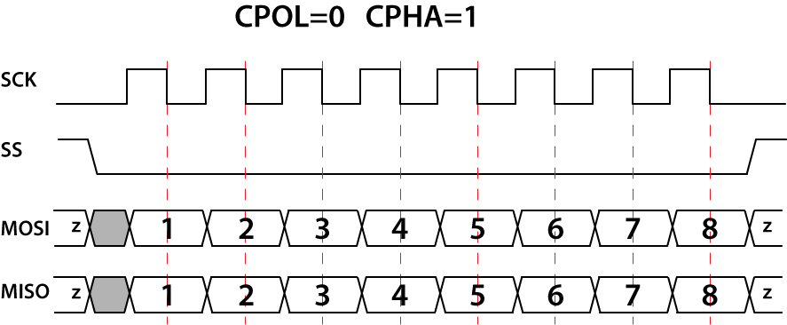
For CPOL=1, the base value of the clock is one. For CPHA=0, data are captured on the clock’s rising edge and data are propagated on a falling edge.
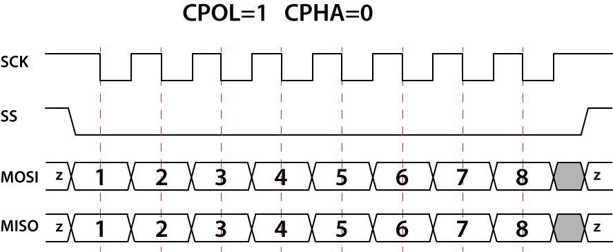
For CPOL=1, the base value of the clock is one. For CPHA=1, data are captured on the clock’s falling edge and data are propagated on a rising edge.

In DLN adapters, the default transmission mode configuration has CPOL=0, CPHA=0 values.
You can specify the mode using the DlnSpiMasterSetMode() function. To configure the CPOL and CPHA values separately, use the DlnSpiMasterSetCpol() and DlnSpiMasterSetCpha() functions.
The master and a slave must use the same set of parameters (clock frequency, CPOL and CPHA); otherwise, a communication will be impossible. If multiple slaves are used, the master configuration should change each time before the master initiates communication with a different slave.
SPI Data Transmission
DLN adapters can operate in the following modes:
Full-duplex – the master sends data to a slave and receives data from the slave simultaneously.
Half-duplex (read) – the master receives data from a slave.
Half-duplex (write) – the master sends data to a slave.
Full-duplex communication
A full-duplex data transmission occurs during each SPI clock cycle: the master transmits data to the slave on the MOSI line and the slave receives it; at the same time, the slave transmits data to the master on the MISO line and the master receives it.

To transmit data in a full-duplex mode, use the DlnSpiMasterReadWrite() function (for 8-bit frames) or the DlnSpiMasterReadWrite16() function (for 9-16-bit frames).
Transmission may continue for any number of clock cycles. When complete, the master idles the clock and releases the SS line. Using the DlnSpiMasterReadWriteEx() function, you can configure whether to release SS line after the transmission or to leave it on the low level.
The DlnSpiMasterReadWriteSS() function allows to select the SS line, transmit data and release the SS line. For details, read Connecting Multiple Slave Devices.
Half-duplex (read) communication
In a half-duplex read mode, the slave transmits data on the MISO line and the master receives it. The MOSI line remains inactive.

To receive data in a half-duplex mode, use the DlnSpiMasterReadEx() function. This function allows to configure whether the SS line should be released after the transmission or left on the low level.
Half-duplex (write) communication
In a half-duplex write mode, the master sends data on the MOSI line and the slave receives it. The MISO line remains inactive.

To send data in a half-duplex mode, use the DlnSpiMasterWriteEx() function. This function allows to configure whether the SS line should be released after the transmission or left on the low level.
In a half-duplex mode, the master can send data to multiple slaves simultaneously. For details, read Connecting Multiple Slave Devices.
Connecting Multiple Slave Devices
In SPI, a master can communicate with a single or multiple slaves. For applications using multiple slaves, the following configurations are possible:
Independent slaves. This is a most common configuration of the SPI bus. The MOSI, MISO and SCK lines of all slaves are interconnected. The SS line of every slave device is connected to a separate pin of SPI master device. Since the MISO pins of the slaves are connected together, they are required to be tristate pins (high, low or high-impedance).
To select the slave, the master pulls the corresponding SS line low. Only one slave can be selected.
For DLN-1 or DLN-2 adapters, you can use the following functions:
- DlnSpiMasterSetSS()
to select the SS line. The SS line value can include only one bit set to 0;
- DlnSpiMasterReadWrite()
to transmit data to/from the slave device;
- DlnSpiMasterReleaseSS()
to release the SS line after transmission if the master does not need to transmit more data to the same slave.
For a DLN-4M adapter, use the DlnSpiMasterReadWriteSS() function – it selects the specified SS line, transmits data and releases the SS line.In a half-duplex read mode, you can also select only one slave. The following functions can be used:
- DlnSpiMasterSetSS()
to select the SS line. The SS line value can include only one bit set to 0;
- DlnSpiMasterReadEx()
to read data from the slave device and to release the SS line after transmission if required.
Independent slave configuration with decoder/demultiplexer. The SS lines are used to send an n-bit value, which is the number of the selected slave. Here, the master can communicate with m=2n slaves.

If you use this configuration, in the DlnSpiMasterSetSS() function the value of the SS lines can include more than one zeros. The demultiplexer converts this value and activates only one SS line.
Half-duplex write configuration. The master transmits data on the MOSI line and the slave receives it. The MISO line remains inactive.

If your slave devices only receive data, you can address multi slaves simultaneously. The following functions can be used:
- DlnSpiMasterSetSS()
to select the SS line; the SS line value can include more than one bits set to 0 (several SS lines can be selected – the master can send data to several slave devices simultaneously);
- DlnSpiMasterWriteEx()
to write data from the slave device(s) and to release the SS line(s) after transmission (optionally).
If the master always sends equal data to some group of slaves in a half-duplex write configuration, all the slaves from the group can be connected to one SS line:

Daisy-chain slaves: the first slave output is connected to the second slave input, etc. The SPI port of each slave is designed to send out during the second group of clock pulses an exact copy of the data it received during the first group of clock pulses.

To check the number of available SS lines in the SPI port, use the DlnSpiMasterGetSSCount() function.
To select the slave, use the DlnSpiMasterSetSS() function. By default, the first SS line (SS0) is selected.
Only one slave can be activated (the signal level on the SS line is low). However, if you use a demultiplexer, you do not select the line, but set the value of the line. The demultiplexer converts this value and selects only one SS line.
The DlnSpiMasterEnable() function enables the selected SS line. Use this function after you configure communication settings.
If you do not need to use all SS lines available in a SPI port, you can disable some of them to use them in other modules. On the contrary, you can enable SS lines that were used for other modules. To disable one SS line, use the DlnSpiMasterSSDisable() function. To disable several SS lines, use the DlnSpiMasterSSMultiDisable() function. To enable one or more SS lines, use the DlnSpiMasterSSEnable() or DlnSpiMasterSSMultiEnable() function accordingly.
SPI Delays
Sometimes slave devices need additional time to process data. In order to provide this time, DLN-series adapters can insert delays at different data transmission stages:
Delay between data frames;
Delay after slave selection;
Delay between slave selections.
All of the delays are set in nanoseconds (ns) and are configured only once. The defined delay values are the same for all SS lines of the port.
Delay between data frames
In case a slave device is not fast enough to process continuously incoming data, you can configure the DLN adapter to insert delays between each two consecutive frames. This gives the slave device additional time to process the data from the previous frame. Once enabled, the delay is inserted after each frame.

The default value of the delay between frames is 0ns. The delay value is adjusted using the DlnSpiMasterSetDelayBetweenFrames() function. The current delay between frames value can be retrieved by calling the DlnSpiMasterGetDelayBetweenFrames() function.
Delay after slave selection
When an SPI slave device needs additional time for initialization, you can configure delay after slave selection (SS). When enabled, the delay is introduces after SS line assertion and before transmission of the first data bit.

The default value of the delay after slave selection is 0ns. To adjust the delay value, use the DlnSpiMasterSetDelayAfterSS() function. To retrieve the current delay value, call the DlnSpiMasterGetDelayAfterSS() function.
Delay between slave selections
Delay between slave selections is inserted after one SS line release and before assertion of another SS line.

The default value of the delay between slave selections is 62ns. The delay value is adjusted using the DlnSpiMasterSetDelayBetweenSS() function, and can be retrieved using the DlnSpiMasterGetDelayBetweenSS() function.
SPI Master Transmission Functions
SPI master interface allows you a wide choice of functions for transmission data. These functions differ:
by operation mode;
by frame size;
by additional attributes.
The following list includes possible functions with brief descriptions:
- DlnSpiMasterReadWrite()
Provides SPI communication in a full-duplex mode (sends and receives data). The function treats data as arrays of 8-bit frames.
- DlnSpiMasterReadWrite16()
Provides SPI communication in a full-duplex mode (sends and receives data). The function treats data as arrays of frames up to 16 bits.
- DlnSpiMasterReadWriteEx()
Provides SPI communication in a full-duplex mode (sends and receives data).The function treats data as arrays of 8-bit frames. When transmission completes, the function can release the SS line or leave it active.
- DlnSpiMasterReadWriteSS()
Provides SPI communication in a full-duplex mode (sends and receives data). The function treats data as arrays of 8-bit frames. The function allows to select the specified SS line. When transmission completes, the function releases the SS line.
- DlnSpiMasterRead()
Provides SPI communication in a half-duplex read mode (receives data). The function treats data as an array of 8-bit frames.
- DlnSpiMasterReadEx()
Provides SPI communication in a half-duplex read mode (receives data). The function treats data as an array of 8-bit frames. When transmission completes, the function can release the SS line or leave it active.
- DlnSpiMasterWrite()
Provides SPI communication in a half-duplex write mode (sends data). The function treats data as an array of 8-bit frames.
- DlnSpiMasterWriteEx()
Provides SPI communication in a half-duplex write mode (sends data). The function treats data as an array of 8-bit frames. When transmission completes, the function can release the SS line or leave it active.
Simple SPI Master Example
The following example shows how to transmit data over SPI bus. For brevity, this example uses default SPI configuration and does not include error detection. You can find the complete example in the “..\Program Files\Diolan\DLN\examples\c_cpp\examples\simple” folder after DLN setup package installation.
- C/C++
#include "..\..\..\common\dln_generic.h"
#include "..\..\..\common\dln_spi_master.h"
#pragma comment(lib, "..\\..\\..\\bin\\dln.lib")

int _tmain(int argc, _TCHAR* argv[])
{
	// Open device
	HDLN device;
	DlnOpenUsbDevice(&device);

	// Set SPI frequency
	uint32_t frequency;
	DlnSpiMasterSetFrequency(device, 0, 100000, &frequency);

	// Enable SPI master
	uint16_t conflict;
	DlnSpiMasterEnable(device, 0, &conflict);

	// Prepare output buffer
	uint8_t input[10], output[10];
	for (int i = 0; i < 10; i++) output[i] = i;

	// Perform SPI transaction
	DlnSpiMasterReadWrite(device, 0, 10, output, input);

	// Print received data
	for (int i = 0; i < 10; i++) printf("%02x ", input[i]);

	// Disable SPI and close device
	DlnSpiMasterDisable(device, 0, 0);
	DlnCloseHandle(device);

	return 0;
}
Line 1:
#include "..\..\..\common\dln_generic.h"The dln_generic..h header file declares functions and data structures for the generic interface.
Line 2:
#include "..\..\..\common\dln_spi_master.h"The
dln_spi_master.hheader file declares functions and data structures for the SPI master interface.Line 3:
#pragma comment(lib, "..\\..\\..\\bin\\dln.lib")Use specified
dln.liblibrary while project linking.Line 9:
DlnOpenUsbDevice(&device);The application establishes the connection with the DLN adapter. This application uses the USB connectivity of the adapter. For additional options, refer to the Device Opening & Identification section.
Line 13:
DlnSpiMasterSetFrequency(device, 0, 100000, frequency);The application configures the frequency of the SPI master port 0. You can also configure SPI transmission mode, frame size, etc. See Configuring the SPI Master Interface for details.
Line 17:
DlnSpiMasterEnable(device, 0, conflict);The application enables the SPI master port 0. The DlnSpiMasterEnable() function assigns the corresponding pins to the SPI master module and configures them. If some other module uses a pin required for the SPI bus interface, the DlnSpiMasterEnable() function returns the
DLN_RES_PIN_IN_USEerror code. Theconflictparameter receives the pin’s number.Lines 21:
for (int i = 0; i < 10; i++) output[i] = i;The application allocates buffers for output and input data. The output buffer is filled with the sequential numbers from 0 to 9.
Line 24:
DlnSpiMasterReadWrite(device, 0, 10, output, input);The DlnSpiMasterReadWrite() function transmits the data to and from the SPI slave device. See the SPI Master Transmission Functions section for additional data transmission functions.
Line 27:
for (int i = 0; i < 10; i++) printf("%02x ", input[i]);The application prints the buffer received from the SPI slave device.
Line 30:
DlnSpiMasterDisable(device, 0);The application releases the SPI master port.
Line 31:
DlnCloseHandle(device);The application closes the handle to the DLN adapter.
SPI Master Functions
The default configuration for the SPI master port is as 8-bit SPI master with CPOL=0 and CPHA=0 transmission parameters. By default, the clock is selected with a frequency of 1Mhz.
Using the SPI master functions allows you to change and check the current SPI master configuration, to control data transmission.
The SPI master functions include the following:
General port information:
- DlnSpiMasterGetPortCount()
Retrieves the number of SPI master ports available in the DLN adapter.
- DlnSpiMasterEnable()
Assigns the selected port to the SPI master module.
- DlnSpiMasterDisable()
Releases the selected SPI master port.
- DlnSpiMasterIsEnabled()
Retrieves whether the selected port is assigned to the SPI master module.
Configuration functions:
- DlnSpiMasterSetFrequency()
Configures the clock frequency for the selected SPI master port.
- DlnSpiMasterGetFrequency()
Retrieves the clock frequency configuration for the SPI master port.
- DlnSpiMasterSetFrameSize()
Configures the size of a single data frame for the selected SPI master port.
- DlnSpiMasterGetFrameSize()
Retrieves the data frame configuration for the selected SPI master port.
- DlnSpiMasterSetMode()
Configures the transmission mode based on CPOL and CPHA values.
- DlnSpiMasterGetMode()
Retrieves the transmission mode configuration for the selected SPI master port.
- DlnSpiMasterSetCpol()
Configures the CPOL value for the selected SPI master port.
- DlnSpiMasterGetCpol()
Retrieves the CPOL value for the selected SPI master port.
- DlnSpiMasterSetCpha()
Configures the CPHA value for the selected SPI master port.
- DlnSpiMasterGetCpha()
Retrieves the CPHA value for the selected SPI master port.
- DlnSpiMasterGetSupportedModes()
Retrieves the supported transmission modes for the selected SPI master port.
- DlnSpiMasterGetSupportedCpolValues()
Retrieves the supported CPOL values for the selected SPI master port.
- DlnSpiMasterGetSupportedCphaValues()
Retrieves the supported CPHA values for the selected SPI master port.
Slave selection functions:
- DlnSpiMasterGetSSCount()
Retrieves the available number of SS lines for the selected SPI master port.
- DlnSpiMasterSetSS()
Selects a Slave Select (SS) line.
- DlnSpiMasterGetSS()
Retrieves the selected SS line.
- DlnSpiMasterSSEnable()
Activates the selected SS line.
- DlnSpiMasterSSDisable()
Disables the selected SS line.
- DlnSpiMasterSSIsEnabled()
Retrieves whether the selected SS line is activated.
- DlnSpiMasterSSMultiEnable()
Activates several selected SS lines.
- DlnSpiMasterSSMultiDisable()
Disables several selected SS lines.
- DlnSpiMasterSSMultiIsEnabled()
Retrieves whether several selected SS lines are activated.
- DlnSpiMasterReleaseSS()
Releases the selected SS line.
- DlnSpiMasterSSBetweenFramesEnable()
Activates releasing SS line between data frames exchanged with a single slave device.
- DlnSpiMasterSSBetweenFramesDisable()
Disables releasing SS line between data frames exchanged with a single slave device.
- DlnSpiMasterSSBetweenFramesIsEnabled()
Retrieves whether releasing SS line between data frames is activated.
Transmission functions:
- DlnSpiMasterReadWrite()
Provides SPI communication in a full-duplex mode with arrays of 8-bit frames.
- DlnSpiMasterReadWrite16()
Provides SPI communication in a full-duplex mode with arrays of frames up to 16 bits.
- DlnSpiMasterReadWriteEx()
Provides SPI communication in a full-duplex mode with arrays of 8-bit frames; can release the SS line after transmission.
- DlnSpiMasterReadWriteSS()
Provides SPI communication in a full-duplex mode with arrays of 8-bit frames; releases the SS line after transmission.
- DlnSpiMasterRead()
Provides SPI communication in a half-duplex read mode with arrays of 8-bit frames.
- DlnSpiMasterReadEx()
Provides SPI communication in a half-duplex read mode with arrays of 8-bit frames; can release the SS line after transmission.
- DlnSpiMasterWrite()
Provides SPI communication in a half-duplex write mode with arrays of 8-bit frames.
- DlnSpiMasterWriteEx()
Provides SPI communication in a half-duplex write mode with arrays of 8-bit frames; can release the SS line after transmission.
Delay functions:
- DlnSpiMasterSetDelayBetweenFrames()
Configures a delay between data frames exchanged with a single slave device.
- DlnSpiMasterGetDelayBetweenFrames()
Retrieves current delay between data frames exchanged with a single slave device.
- DlnSpiMasterSetDelayAfterSS()
Configures a delay between activating SS line and the first data frame.
- DlnSpiMasterGetDelayAfterSS()
Retrieves current delay between activating SS line and the first data frame.
- DlnSpiMasterSetDelayBetweenSS()
Configures a minimum delay between releasing one SS line and activating another SS line.
- DlnSpiMasterGetDelayBetweenSS()
Retrieves current delay between releasing one SS line and activating another SS line.
The dln_spi_master.h file declares the SPI Master Interface functions.
DlnSpiMasterGetPortCount() Function
The DlnSpiMasterGetPortCount() function retrieves the total number of SPI master ports available in your DLN-series adapter.
DlnSpiMasterEnable() Function
The DlnSpiMasterEnable() function activates the selected SPI master port on your DLN-series adapter.
DlnSpiMasterDisable() Function
The DlnSpiMasterDisable() function releases the selected SPI master port on your DLN-series adapter.
DlnSpiMasterIsEnabled() Function
The DlnSpiMasterIsEnabled() function retrieves whether the specified SPI master port is activated.
DlnSpiMasterSetFrequency() Function
The DlnSpiMasterSetFrequency() function sets the clock frequency on the SCK line, used to synchronize data transmission between master and slave devices.
DlnSpiMasterGetFrequency() Function
The DlnSpiMasterGetFrequency() function retrieves the current setting for SPI clock frequency.
DlnSpiMasterSetFrameSize() Function
The DlnSpiMasterSetFrameSize() function sets the size of a single SPI data frame.
DlnSpiMasterGetFrameSize() Function
The DlnSpiMasterGetFrameSize() function retrieves the current size setting for SPI data frame.
DlnSpiMasterSetMode() Function
The DlnSpiMasterSetMode() function sets SPI transmission parameters (CPOL and CPHA).
DlnSpiMasterGetMode() Function
The DlnSpiMasterGetMode() function retrieves current configuration of the selected SPI master port.
DlnSpiMasterSetCpol() Function
The DlnSpiMasterSetCpol() function sets the clock polarity value.
DlnSpiMasterGetCpol() Function
The DlnSpiMasterGetCpol() function retrieves the current value of clock polarity (CPOL).
DlnSpiMasterSetCpha() Function
The DlnSpiMasterSetCpha() function allows to set clock phase (CPHA) value.
DlnSpiMasterGetCpha() Function
The DlnSpiMasterGetCpha() function retrieves the current value of clock phase (CPHA).
DlnSpiMasterGetSupportedModes() Function
The DlnSpiMasterGetSupportedModes() function retrieves all supported SPI master modes (CPOL and CPHA values). For more information, read Clock Phase and Polarity.
DlnSpiMasterGetSupportedCpolValues() Function
The DlnSpiMasterGetSupportedCpolValues() function retrieves supported CPOL values.
DlnSpiMasterGetSupportedCphaValues() Function
The DlnSpiMasterGetSupportedCphaValues() function retrieves the available CPHA values.
DlnSpiMasterGetSSCount() Function
The DlnSpiMasterGetSSCount() function returns the available number of SS lines.
DlnSpiMasterSetSS() Function
The DlnSpiMasterSetSS() function selects a Slave Select (SS) line.
DlnSpiMasterGetSS() Function
The DlnSpiMasterGetSS() function retrieves current Slave Select (SS) line.
DlnSpiMasterSSEnable() Function
The DlnSpiMasterSSEnable() function enables the specified SS line.
DlnSpiMasterSSDisable() Function
The DlnSpiMasterSSDisable() function disables the specified SS line.
DlnSpiMasterSSIsEnabled() Function
The DlnSpiMasterSSIsEnabled() function enables the specified SS line.
DlnSpiMasterSSMultiEnable() Function
The DlnSpiMasterSSMultiEnable() function enables the specified SS lines.
DlnSpiMasterSSMultiDisable() Function
The DlnSpiMasterSSMultiDisable() function enables the specified SS lines.
DlnSpiMasterSSMultiIsEnabled() Function
The DlnSpiMasterSSMultiIsEnabled() function enables the specified SS lines.
DlnSpiMasterReleaseSS() Function
The DlnSpiMasterReleaseSS() function releases SS lines.
DlnSpiMasterSSBetweenFramesEnable() Function
The DlnSpiMasterSSBetweenFramesEnable() function enables release of an SS line between data frames exchanged with a single slave device.
DlnSpiMasterSSBetweenFramesDisable() Function
The DlnSpiMasterSSBetweenFramesDisable() function disables release of an SS line between data frames exchanged with a single slave device.
DlnSpiMasterSSBetweenFramesIsEnabled() Function
The DlnSpiMasterSSBetweenFramesIsEnabled() function checks whether the DLN-series adapter releases SS line between successive SPI frames transmission.
DlnSpiMasterReadWrite() Function
The DlnSpiMasterReadWrite() function sends and receives data via SPI bus. The received and sent data are arrays of 1-byte elements. This function is suited to transmit data frames of 8 bits or less. In case you set a frame size more than 8 bits, it is advised to use the DlnSpiMasterReadWrite16() function.
DlnSpiMasterReadWrite16() Function
The DlnSpiMasterReadWrite16() function sends and receives 2-byte frames via SPI bus.
DlnSpiMasterReadWriteSS() Function
The DlnSpiMasterReadWriteSS() function selects the specified SS line, transmits data via SPI bus and releases the SS line.
DlnSpiMasterReadWriteEx() Function
The DlnSpiMasterReadWriteEx() function sends and receives data via SPI bus. The data is transmitted as an array of 1-byte elements. In this function you can use additional attributes to configure the SS line state after data transmission.
DlnSpiMasterRead() Function
The DlnSpiMasterRead() function receives data via SPI bus. The received data is an array of 1-byte elements.
DlnSpiMasterReadEx() Function
The DlnSpiMasterReadEx() function receives data via SPI bus. The received data is an array of 1-byte elements. In this function you can use additional attributes to configure the SS line state after data transmission.
DlnSpiMasterWrite() Function
The DlnSpiMasterWrite() function sends data via SPI bus. The data is sent as an array of 1-byte elements.
DlnSpiMasterWriteEx() Function
The DlnSpiMasterWriteEx() function sends data via SPI bus. The data is sent as an array of 1-byte elements. By using this function you can use additional attributes.
DlnSpiMasterSetDelayBetweenFrames() Function
The DlnSpiMasterSetDelayBetweenFrames() function sets a delay between data frames exchanged with a single slave device. For more information, read SPI Delays.
DlnSpiMasterGetDelayBetweenFrames() Function
The DlnSpiMasterGetDelayBetweenFrames() function retrieves current setting for delay between data frames exchanged with a single slave device.
DlnSpiMasterSetDelayAfterSS() Function
The DlnSpiMasterSetDelayAfterSS() function sets a delay duration between assertion of an SS line and first data frame. For more information, read SPI Delays.
DlnSpiMasterGetDelayAfterSS() Function
The DlnSpiMasterGetDelayAfterSS() function retrieves the current setting for minimum delay between assertion of an SS line and the first data frame.
DlnSpiMasterSetDelayBetweenSS() Function
The DlnSpiMasterSetDelayBetweenSS() function sets a minimum delay between release of an SS line and assertion of another SS line. For more information, read SPI Delays.
DlnSpiMasterGetDelayBetweenSS() Function
The DlnSpiMasterGetDelayBetweenSS() function retrieves the current setting for minimum delay after one SS line is released and before another SS line is asserted.
SPI Slave Interface
Some DLN-series adapters support the SPI Slave Interface.
Configuring the Slave for Communication
To configure the slave for the communication, follow these steps:
Configure SS idle timeout. When you enable the SPI slave, the SS line may be busy. The DLN adapter waits until the SS line drives high. If the SS line is not released during the SS idle timeout, the SPI slave cannot be enabled. Read SS Idle Timeout.
Configure the transmission mode (clock polarity and clock phase). The clock polarity (CPOL) and clock phase (CPHA) configuration must be the same for both SPI master and SPI slave devices.
Configure loading data to the reply buffer. The reply mode and reply type parameters can prevent from losing data if the frame size, configured by you for the SPI slave, does not correspond the frame size set on the SPI master. Read SPI Slave Reply Buffer.
If needed, configure events. DLN adapters provide event-driven interface for SPI slave devices. Read SPI Slave Events.
SS Idle Timeout
When you try to enable the SPI slave module, the SS line can appear busy. To prevent transmitting incorrect data, the DLN adapter idles until the SS line is released (drives high). Only then, the SPI slave can be enabled.
To limit the idle time, you can specify the idle timeout value in milliseconds (ms) by calling the DlnSpiSlaveSetSSIdleTimeout() function. The default value is 100ms. The idle timeout can be from 1ms to 1000ms. If during the specified idle timeout the SS line was not released, the DlnSpiSlaveEnable() function returns the DLN_RES_SPI_SLAVE_SS_IDLE_TIMEOUT error.
For details about idle event timeout, read DLN_SPI_SLAVE_EVENT_IDLE Events.
SPI Slave Reply Buffer
When the master initiates transmission, the DLN adapter-slave fills the reply buffer with data that should be sent to the master. To fill the reply buffer, you can use the following functions: DlnSpiSlaveLoadReply() or DlnSpiSlaveEnqueueReply(). The DlnSpiSlaveLoadReply() function clears the buffer and makes the current reply the first in the queue. In contrast, the DlnSpiSlaveEnqueueReply() function puts the current reply to the end of the queue.
Transmitted data is limited to the number of frames received by the master. The sizes of slave buffer (reply buffer) and master buffer (received buffer) may differ.
If the reply buffer size exceeds the received buffer size, the last bytes of the reply buffer can be lost or sent with the following transmission. It depends on the reply mode you configure. For more information, read Reply Modes.
If the reply buffer size is less than the received buffer size, the last bytes can be filled by zeroes or by repeated reply bytes. It depends on the shortage action you configure. For details, read Reply Shortage Actions.
Reply Modes
If the reply buffer size exceeds the size of the buffer received by the master, the following options are possible:
If the last bytes of the reply are not weighty, they can be rejected. In this case, the master receives the bytes from the reply buffer until the SS line rises. The last bytes of the reply buffer are lost. This mode is called
DLN_SPI_SLAVE_REPLY_MODE_SS_BASED.If you do not want to lose any data, the last buffers can be added to the queue. In this case, the master receives the bytes from the reply buffer until the SS line rises. The last bytes of the reply buffer are not lost, they are added to the queue and the master receives them with the next transmission. This mode is called
DLN_SPI_SLAVE_REPLY_MODE_COUNT_BASED.
You have two loaded replies: ABCD and EF12. The master initiates two transmissions of 3 words in each. From the slave, the master receives the following:
In the
DLN_SPI_SLAVE_REPLY_MODE_SS_BASEDmode, the master receivesABCandEF1. The last bytes of every reply are lost.
In the
DLN_SPI_SLAVE_REPLY_MODE_COUNT_BASEDmode, the master receivesABCandDEF. The last bytes of the second reply is queued for the following transmissions.
To configure the reply mode, use the DlnSpiSlaveSetReplyMode() function. The DlnSpiSlaveGetSupportedReplyModes() function retrieves all supported reply modes.
Reply Shortage Actions
If the reply buffer size is less than the size of the buffer received by the master, the missed bytes can be filled by zeroes (the DLN_SPI_SLAVE_REPLY_SHORTAGE_SEND_ZEROES reply type) or by repeating the reply bytes (the DLN_SPI_SLAVE_REPLY_SHORTAGE_REUSE reply type).
You have a loaded reply: ABCD. The master initiates a transmission of 6 words. From the slave, the master receives the following:
If the
DLN_SPI_SLAVE_REPLY_SHORTAGE_SEND_ZEROESreply type is set, the master receivesABCD00. The last bytes are filled with zeroes.
If the
DLN_SPI_SLAVE_REPLY_SHORTAGE_REUSEreply type is set, the master receivesABCDAB. The last bytes are filled by repeating the first bytes of the reply.
SPI Slave Events
DLN adapters-slaves can be configured to send events. The events are generated when the slave meets the certain predefined conditions.
DLN adapters-slaves support the following events:
| Event Type | Description |
| A DLN adapter does not generate any events. |
| A DLN adapter generates events when the level on the SS line rises. For details, read DLN_SPI_SLAVE_EVENT_SS_RISE Events. |
| A DLN adapter generates events when the buffer is full. For details, read DLN_SPI_SLAVE_EVENT_BUFFER_FULL Events. |
| A DLN adapter generates events when the slave idles for the configured time. For details, read DLN_SPI_SLAVE_EVENT_IDLE Events. |
When an event occurs, your application is notified (see the Notifications section). Call the DlnGetMessage() function to obtain the event details. The DLN_SPI_SLAVE_DATA_RECEIVED_EV structure describes this information.
By default, event generation is disabled (DLN_SPI_SLAVE_EVENT_NONE).
DLN_SPI_SLAVE_EVENT_SS_RISE Events
A DLN adapter generates the DLN_SPI_SLAVE_EVENT_SS_RISE events each time the level on the SS line rises.

When the transmission from/to the SPI master completes, the master rises the level on the SS line. At this moment, a DLN adapter-slave generates the DLN_SPI_SLAVE_EVENT_SS_RISE event. After receiving this event, your application can perform certain actions, for example, show received data or start processing them.
The eventCount field of the first event is set to zero. For every new DLN_SPI_SLAVE_EVENT_SS_RISE event, the eventCount field increments. When you reset the slave or change its configuration, the eventCount filed is reset to zero.
Use the DlnSpiSlaveEnableSSRiseEvent() function to enable generating these events. To disable this event, use the DlnSpiSlaveDisableSSRiseEvent() function. The DlnSpiSlaveIsSSRiseEventEnabled() function allows to check whether this event is enabled.
DLN_SPI_SLAVE_EVENT_BUFFER_FULL Events
A DLN adapter generates the DLN_SPI_SLAVE_EVENT_BUFFER_FULL events each time the buffer becomes full.

You can configure the buffer size by calling the DlnSpiSlaveSetEventSize() function. The supported values are from 1 to 256 bytes. By default, the size parameter is set to 256 bytes. To check the current value, use the DlnSpiSlaveGetEventSize() function.
During the transmission from the SPI master, if the buffer is overfilled, a DLN adapter-slave generates the DLN_SPI_SLAVE_EVENT_BUFFER_FULL event.
The eventCount field of the first event is set to zero. For every new DLN_SPI_SLAVE_EVENT_SS_RISE event, the eventCount field increments. When you reset the slave or change its configuration, the eventCount filed is reset to zero.
Use the DlnSpiSlaveEnableEvent() function to enable generating these events. To disable this event, use the DlnSpiSlaveDisableEvent() function. The DlnSpiSlaveIsEventEnabled() function allows to check whether this event is enabled.
The DLN_SPI_SLAVE_EVENT_BUFFER_FULL event does not conflict with other events.
DLN_SPI_SLAVE_EVENT_IDLE Events
A DLN adapter generates the DLN_SPI_SLAVE_EVENT_IDLE events each time the SS line stays raised for a certain time.

When the transmission from/to the SPI master completes, the master rises the level on the SS line. If the level stays high for the time set in the timeout parameter, a DLN adapter-slave generates the DLN_SPI_SLAVE_EVENT_IDLE event. If the SS line stays in the high level less than the required idle timeout, the event does not occur.
To configure the timeout parameter, use the DlnSpiSlaveSetIdleEventTimeout() function. The DlnSpiSlaveSetIdleEventTimeout() function allows to check the current value of this parameter.
Use the DlnSpiSlaveEnableIdleEvent() function to enable generating DLN_SPI_SLAVE_EVENT_IDLE events. To disable this event, use the DlnSpiSlaveDisableIdleEvent() function. The DlnSpiSlaveIsIdleEventEnabled() function allows to check whether this event is enabled.
SPI Slave Functions
The default configuration for the SPI slave port is as 8-bit SPI slave with CPOL=0 and CPHA=0 transmission parameters. By default, no events are generated.
Using the SPI slave functions allows you to change and check the current SPI slave configuration, to control data transmission.
The SPI slave functions include the following:
General port information:
- DlnSpiSlaveGetPortCount()
Retrieves the number of SPI slave ports available in the DLN adapter.
- DlnSpiSlaveEnable()
Assigns the selected port to the SPI slave module.
- DlnSpiSlaveDisable()
Releases the selected SPI slave port.
- DlnSpiSlaveIsEnabled()
Retrieves whether the selected port is assigned to the SPI slave module.
Configuration functions:
- DlnSpiSlaveSetSSIdleTimeout()
Specifies idle timeout for releasing the SS line.
- DlnSpiSlaveGetSSIdleTimeout()
Retrieves the idle timeout setting.
- DlnSpiSlaveSetFrameSize()
Specifies the data frame size for the selected SPI slave port.
- DlnSpiSlaveGetFrameSize()
Retrieves the current frame size for the selected SPI slave port.
- DlnSpiSlaveGetSupportedFrameSizes()
Retrieves the supported frame sizes.
- DlnSpiSlaveSetMode()
Specifies transmission parameters (CPOL and CPHA) for the selected SPI slave port.
- DlnSpiSlaveGetMode()
Retrieves the current transmission parameters (CPOL and CPHA) for the selected SPI slave port.
- DlnSpiSlaveGetSupportedModes()
Retrieves the supported transmission parameters (CPOL and CPHA).
- DlnSpiSlaveSetCpha()
Specifies CPHA value for the selected SPI slave port.
- DlnSpiSlaveGetCpha()
Retrieves the current CPHA value for the selected SPI slave port.
- DlnSpiSlaveGetSupportedCphaValues()
Retrieves the supported CPHA values.
- DlnSpiSlaveSetCpol()
Specifies CPOL value for the selected SPI slave port.
- DlnSpiSlaveGetCpol()
Retrieves the current CPOL value for the selected SPI slave port.
- DlnSpiSlaveGetSupportedCpolValues()
Retrieves the supported CPOL values.
Reply functions:
- DlnSpiSlaveLoadReply()
Clears the buffer and makes the current reply the first in the queue.
- DlnSpiSlaveEnqueueReply()
Puts the current reply to the end of the queue.
- DlnSpiSlaveSetReplyMode()
Specifies actions if the reply buffer size exceeds the size of the buffer received by the master.
- DlnSpiSlaveGetReplyMode()
Retrieves the current reply configuration.
- DlnSpiSlaveGetSupportedReplyModes()
Retrieves the supported reply modes.
- DlnSpiSlaveSetReplyShortageAction()
Specifies actions if the reply buffer size is less than the size of the buffer received by the master.
- DlnSpiSlaveGetReplyShortageAction()
Retrieves the current for reply shortage action settings.
- DlnSpiSlaveGetSupportedShortageActions()
Retrieves the supported reply shortage actions.
Event configuration:
- DlnSpiSlaveEnableSSRiseEvent()
Enables generating events when the level on the SS line rises.
- DlnSpiSlaveDisableSSRiseEvent()
Disables generating events when the level on the SS line rises.
- DlnSpiSlaveIsSSRiseEventEnabled()
Retrieves the current configuration for generating events when the level on the SS line rises.
- DlnSpiSlaveEnableEvent()
Enables generating events when the buffer is full.
- DlnSpiSlaveDisableEvent()
Disables generating events when the buffer is full.
- DlnSpiSlaveIsEventEnabled()
Retrieves the current configuration for generating events when the buffer is full.
- DlnSpiSlaveSetEventSize()
Specifies the buffer size.
- DlnSpiSlaveGetEventSize()
Retrieves the current buffer size.
- DlnSpiSlaveEnableIdleEvent()
Enables generating events when the slave idles for the configured time.
- DlnSpiSlaveDisableEvent()
Disables generating events when the slave idles for the configured time.
- DlnSpiSlaveIsEventEnabled()
Retrieves the current configuration for generating events when the slave idles for the configured time.
- DlnSpiSlaveSetIdleEventTimeout()
Specifies the timeout value.
- DlnSpiSlaveGetIdleEventTimeout()
Retrieves the current timeout value.
- DlnSpiSlaveGetMinIdleEventTimeout()
Retrieves the minimum timeout value.
- DlnSpiSlaveGetMaxIdleEventTimeout()
Retrieves the maximum timeout value.
The dln_spi_slave.h file declares the SPI Salve Interface functions.
DlnSpiSlaveGetPortCount() Function
The DlnSpiSlaveGetPortCount() function retrieves the total number of SPI slave ports available at your DLN-series adapter.
DlnSpiSlaveEnable() Function
The DlnSpiSlaveEnable() function activates the specified SPI slave port at your DLN-series adapter.
DlnSpiSlaveDisable() Function
The DlnSpiSlaveDisable() function deactivates the specified SPI slave port on your DLN adapter.
DlnSpiSlaveIsEnabled() Function
The DlnSpiSlaveIsEnabled() function retrieves information whether the specified SPI slave port is active or not.
DlnSpiSlaveSetSSIdleTimeout() Function
The DlnSpiSlaveSetSSIdleTimeout() function sets SS idle timeout. For details, read SS Idle Timeout.
DlnSpiSlaveGetSSIdleTimeout() Function
The DlnSpiSlaveGetSSIdleTimeout() function retrieves the current value of SS idle timeout.
DlnSpiSlaveSetFrameSize() Function
The DlnSpiSlaveSetFrameSize() function sets the size of a single SPI data frame.
DlnSpiSlaveGetFrameSize() Function
The DlnSpiSlaveGetFrameSize() function retrieves the current size setting for SPI data frames.
DlnSpiSlaveGetSupportedFrameSizes() Function
The DlnSpiSlaveGetSupportedFrameSizes() function returns all supported frame size values.
DlnSpiSlaveSetMode() Function
The DlnSpiSlaveSetMode() function sets SPI transmission parameters (CPOL and CPHA). For more information, read Clock Phase and Polarity.
DlnSpiSlaveGetMode() Function
The DlnSpiSlaveGetMode() function retrieves the current transmission parameters (CPOL and CPHA) for the specified SPI slave port. For details, read Clock Phase and Polarity.
DlnSpiSlaveGetSupportedModes() Function
The DlnSpiSlaveGetSupportedModes() function retrieves all supported SPI slave modes.
DlnSpiSlaveSetCpha() Function
The DlnSpiSlaveSetCpha() function allows to set the clock phase (CPHA) value.
DlnSpiSlaveGetCpha() Function
The DlnSpiSlaveGetCpha() function retrieves the current value of clock phase (CPHA).
DlnSpiSlaveGetSupportedCphaValues() Function
The DlnSpiSlaveGetSupportedCphaValues() function retrieves all supported CPHA (clock phase) values.
DlnSpiSlaveSetCpol() Function
The DlnSpiSlaveSetCpol() function allows to set the clock polarity (CPOL) value.
DlnSpiSlaveGetCpol() Function
The DlnSpiSlaveGetCpol() function retrieves the current value of clock polarity (CPOL).
DlnSpiSlaveGetSupportedCpolValues() Function
The DlnSpiSlaveGetSupportedCpolValues() function retrieves all supported CPOL (clock polarity) values.
DlnSpiSlaveLoadReply() Function
The DlnSpiSlaveLoadReply() function loads data (loads a number of bytes to reply buffer) to be transmitted to an SPI-master device. This function clears the buffer and makes the current reply the first in the queue.
DlnSpiSlaveEnqueueReply() Function
The DlnSpiSlaveEnqueueReply() function adds a buffer to queue.
DlnSpiSlaveSetReplyMode() Function
The DlnSpiSlaveSetReplyMode() function sets SPI slave reply mode.
DlnSpiSlaveGetReplyMode() Function
The DlnSpiSlaveGetReplyMode() function retrieves the current SPI slave reply mode.
DlnSpiSlaveGetSupportedReplyModes() Function
The DlnSpiSlaveGetSupportedReplyModes() function retrieves the supported SPI slave reply modes.
DlnSpiSlaveSetReplyShortageAction() Function
The DlnSpiSlaveSetReplyShortageAction() function sets the reply shortage action value. When the master sends a data block that is larger than the loaded reply, this function specifies how to fill empty bytes (repeat the reply bytes or send zeroes).
DlnSpiSlaveGetReplyShortageAction() Function
The DlnSpiSlaveGetReplyShortageAction() functions retrieves the current value of reply shortage action.
DlnSpiSlaveGetSupportedShortageActions() Function
The DlnSpiSlaveGetSupportedShortageActions() function retrieves supported shortage action values.
DlnSpiSlaveEnableSSRiseEvent() Function
The DlnSpiSlaveEnableSSRiseEvent() function activates event on SS rising edge.
DlnSpiSlaveDisableSSRiseEvent() Function
The DlnSpiSlaveDisableSSRiseEvent() function deactivates SS rise events.
DlnSpiSlaveIsSSRiseEventEnabled() Function
The DlnSpiSlaveIsSSRiseEventEnabled() function retrieves information whether the SS rise events are active or not.
DlnSpiSlaveEnableEvent() Function
The DlnSpiSlaveEnableEvent() function activates SPI slave buffer full event.
DlnSpiSlaveDisableEvent() Function
The DlnSpiSlaveDisableEvent() function deactivates SPI slave buffer full event.
DlnSpiSlaveIsEventEnabled() Function
The DlnSpiSlaveIsEventEnabled() function retrieves information whether the SPI slave events are active or not.
DlnSpiSlaveSetEventSize() Function
The DlnSpiSlaveSetEventSize() function sets the event buffer size.
DlnSpiSlaveGetEventSize() Function
The DlnSpiSlaveGetEventSize() function retrieves value of current event buffer size.
DlnSpiSlaveEnableIdleEvent() Function
The DlnSpiSlaveEnableIdleEvent() function activates the SPI slave idle event.
DlnSpiSlaveDisableIdleEvent() Function
The DlnSpiSlaveDisableIdleEvent() function deactivates the SPI slave idle event.
DlnSpiSlaveIsIdleEventEnabled() Function
The DlnSpiSlaveIsIdleEventEnabled() function activates the SPI slave idle event.
DlnSpiSlaveSetIdleEventTimeout() Function
The DlnSpiSlaveSetIdleEventTimeout() function sets idle event timeout.
DlnSpiSlaveGetIdleEventTimeout() Function
The DlnSpiSlaveGetIdleEventTimeout() function retrieves the current value of idle event timeout.
DlnSpiSlaveGetMinIdleEventTimeout() Function
The DlnSpiSlaveGetMinIdleEventTimeout() function retrieves the minimum value of idle event timeout.
DlnSpiSlaveGetMaxIdleEventTimeout() Function
The DlnSpiSlaveGetMaxIdleEventTimeout() function retrieves the maximum value of idle event timeout.
GPIO Interface
DLN series interface adapters contain a large number of pins that you can use as general-purpose inputs and outputs. Some of these pins are shared between GPIO (general-purpose input/output) and other modules (I2C, SPI). If you do not the corresponding pins to other modules, you can configure them as digital inputs or digital outputs and control them.
If you configure pins as inputs, your application reads the digital value set by the external device. If you define pins as outputs, your application can control the digital value on these pins.
To use a pin as a digital input or a digital output, the pin must be assigned to the GPIO module by using the DlnGpioPinEnable() function. You can use the DlnGpioPinIsEnabled() function, to check whether a pin is already assigned to the GPIO module.
You cannot assign a pin to the GPIO module if another module uses it. Call the DlnGetPinCfg() function to check which module uses a pin.
Most of the DLN-series adapters provide additional functionality for GPIO pins. You can configure the following features for any input and/or output pin individually:
Event-driven interface. You can configure a digital input pin to raise events when the value on this pin changes. There are several configuration options - what kind of events and when should be generated. For more details, read Digital Input Events.
Debounce filter. If you do not want to treat casual pulses as value changes, you can enable the debounce filter, which rejects pulses less that the predefined debounce period. For details, read Debounce Filter.
Open drain mode. If you interconnect several outputs on a single I/O line, they may settle different values simultaneously and cause hardware damage. The open drain mode helps you to avoid this. For details, read Open Drain Mode.
Pull-up and pull-down resistors. When no external hardware is connected to an input line, the logic level on this line is undefined. Use pull-up or pull-down resistors to ensure that inputs to I/O lines are settled at expected levels. For details, read Pull-up/Pull-down Resistors.
Digital Outputs
You can configure most of the DLN-series adapter pins as general-purpose digital outputs. Call the DlnGpioPinSetDirection() function and pass 1 for the direction parameter to configure the GPIO pin as a digital output. You can call this function either before or after the pin is assigned to the GPIO module by using the DlnGpioPinEnable() function.
To set the value on the pin, use the DlnGpioPinSetOutVal() function. Call the DlnGpioPinGetOutVal()function to retrieve the output value configured for this pin. The actual value of the pin may differ from the configured one (for example, when the pin is in the open drain mode or it is not assigned to the GPIO module). The DlnGpioPinGetVal()function retrieves the actual value present on the pin.
For digital outputs, you can use the Open Drain Mode.
Use the following GPIO Interface functions to control and monitor output pins:
- DlnGpioPinSetDirection()
Configures a pin as a digital output. Pass 1 for the
directionparameter.- DlnGpioPinSetOutVal()
Sets the output value for the pin.
- DlnGpioPinGetOutVal()
Retrieves the output value configured for the pin.
- DlnGpioPinGetVal()
Retrieves the actual value on the I/O line.
Digital Inputs
You can configure most of the DLN-series adapter pins as general-purpose digital inputs. Call the DlnGpioPinSetDirection() function and pass 0 for the direction parameter to configure the GPIO pin as a digital input. You can call this function either before or after the pin is assigned to the GPIO module by using the DlnGpioPinEnable() function.
You can check a pin direction by using the DlnGpioPinGetDirection() function.
The default pin direction is set to input (value 0).
To check the value on the pin, use the DlnGpioPinGetVal() function.
For digital inputs, you can use the following features:
Use the following GPIO Interface functions to control and monitor input pins:
- DlnGpioPinSetDirection()
Configures a pin as a digital input. Pass 0 for the
directionparameter.- DlnGpioPinGetVal()
Retrieves the value on the I/O line.
Digital Input Events
There are two ways of monitoring changes on the digital input line:
To poll the input pin periodically. In this case, you can potentially miss an input if your application reads the value at the wrong time.
To receive events when the input value changes. You can configure event generation for specific changes, for example, when the level on a pin rises. You can also configure the adapter to generate events periodically.
To configure events, use the DlnGpioPinSetEventCfg() function. You need to specify the eventType and the eventPeriod parameters. The DlnGpioPinGetSupportedEventTypes() function returns the list of event types available for a pin.
The eventType parameter can have one of the following values:
| Event Type | Description |
DLN_GPIO_EVENT_NONE | A DLN adapter does not generate any events. |
DLN_GPIO_EVENT_CHANGE | A DLN adapter generates events when the level on the digital input line changes. For details, read DLN_GPIO_EVENT_CHANGE Events |
DLN_GPIO_EVENT_LEVEL_HIGH | A DLN adapter generates events when the high level is present on the digital input line or after transition from low to high level. For details, read DLN_GPIO_EVENT_LEVEL_HIGH Events |
DLN_GPIO_EVENT_LEVEL_LOW | A DLN adapter generates events when the low level is present on the digital input line or after transition from high to low level. For details, read DLN_GPIO_EVENT_LEVEL_LOW Events |
DLN_GPIO_EVENT_ALWAYS | A DLN adapter generates events continuously, regardless of the level. For details, read DLN_GPIO_EVENT_ALWAYS Events |
The eventPeriod parameter defines the interval between repeated events in milliseconds (ms). This parameter must be non-zero for the DLN_GPIO_EVENT_ALWAYS events. For other events, this parameter is optional.
If the Debounce Filter in enabled on a pin, the level change event is generated after the debounce filter accepts a new value.
You can configure events for each input pin individually. If the pin is configured as a digital input, the new settings are applied immediately. If you configure events when a pin is defined as an output or is not assigned to the GPIO module at all, this configuration is saved in the internal memory and is applied when the pin becomes a GPIO input.
When an event occurs, your application is notified (see the Notifications section). Call the DlnGetMessage() function to obtain the event details. The DLN_GPIO_CONDITION_MET_EV structure describes this information.
By default, event generation is disabled for all pins (the eventType parameter is set to DLN_GPIO_EVENT_NONE).
The following GPIO Interface functions can be used to control and monitor events:
- DlnGpioPinSetEventCfg()
Configures event generation for a pin.
- DlnGpioPinGetEventCfg()
Retrieves event generation configuration for a pin.
- DlnGpioPinGetSupportedEventTypes()
Returns the list of the event types available for a pin.
DLN_GPIO_EVENT_CHANGE Events
A DLN adapter generates the DLN_GPIO_EVENT_CHANGE events each time the level on the input pin changes.

Use the DlnGpioPinSetEventCfg()function to configure events. Pass DLN_GPIO_EVENT_CHANGE for the eventType parameter.
If the eventPeriod parameter is zero, the DLN adapter generates single events when the level on the input pin changes.
If the eventPeriod is non-zero, the DLN adapter resents the events periodically with the eventPeriod interval while the level on the pin remains unchanged (a series of events).

A series of e vents begins when the level on the GPIO line changes. At this moment, the DLN adapter sends the first event in the series. The eventCount field of the first event is set to zero and the value field contains the actual value on the GPIO line. Then, while the level on the GPIO line remains unchanged, the DLN adapter repeatedly sends events with the same value in the value field. The interval between recurring events is equal to eventPeriod milliseconds. The eventCount field increments for each event in the series. You can use this field to calculate the time passed from the last level change (time = eventCount * eventPeriod).When the level on the GPIO line changes, a new series of events begins. The eventCount field is reset to zero and the value field is set to the actual value present on the line after the change.
DLN_GPIO_EVENT_LEVEL_HIGH Events
A DLN adapter generates the DLN_GPIO_EVENT_LEVEL_HIGH events each time the level on the input pin rises.

Use the DlnGpioPinSetEventCfg()function to configure events. Pass DLN_GPIO_EVENT_LEVEL_HIGH for the eventType parameter.
If the eventPeriod is zero, the DLN adapter generates single events when the level on the input pin rises (after transition from low to high level).
If the eventPeriod is non-zero , the DLN adapter resents events periodically with the eventPeriod interval while the level is high:

A series of events begins when the level on the GPIO line rises. At this moment, the DLN adapter sends the first event in the series. The eventCount field of the first event is set to zero and the value field is set to 1 to reflect the actual value on the GPIO line. Then, while the level on the GPIO line remains high, the DLN adapter repeatedly sends events. The same value in the value field stays the same. The eventCount field increments for every new event. The interval between recurring events is equal to eventPeriod milliseconds. You can calculate the time passed from the last level rise (time = eventCount * eventPeriod).
When the level on the GPIO line drops, the series of events ends. When the level on the line rises again, a new series of events begins. The eventCount field is reset to zero.
DLN_GPIO_EVENT_LEVEL_LOW Events
A DLN adapter generates the DLN_GPIO_EVENT_LEVEL_LOW events each time the level on the input pin drops.

Use the DlnGpioPinSetEventCfg()function to configure events. Pass DLN_GPIO_EVENT_LEVEL_LOW for the eventType parameter.
If the eventPeriod is zero, the DLN adapter generates single events when the level on the input pin drops (after transition from high to low level).
If the eventPeriod is non-zero, the DLN adapter resents events periodically with the eventPeriod interval while the level is low.

A series of events begins when the level on the GPIO line drops. At this moment, the DLN adapter sends the first event in the series. The eventCount field of the first event is set to zero and the value field contains 0 to reflect the actual value on the GPIO line. Then, while the level on the GPIO line remains low, the DLN adapter repeatedly sends events. The value in the value field stays the same. The eventCount field increments for every new event. The interval between recurring events is equal to eventPeriod milliseconds. You can calculate the time passed from the last level lowering (time = eventCount * eventPeriod).
When the level on the GPIO line rises, the series of events ends. When the level on the line drops again, a new series of events begins. The eventCount field is reset to zero.
DLN_GPIO_EVENT_ALWAYS Events
A DLN adapter generates the DLN_GPIO_EVENT_ALWAYS events periodically with the eventPeriod interval regardless of the level on the pin and its changes. This event notifies the current signal level on a pin.

Call the DlnGpioPinSetEventCfg()function to configure events. Specify DLN_GPIO_EVENT_ALWAYS as the eventType parameter.
For the DLN_GPIO_EVENT_ALWAYS events, the eventPeriod parameter is required to be non-zero.
Immediately after you configure the DLN_GPIO_EVENT_ALWAYS event, the DLN adapter sends the first event. The eventCount field is set to zero and the value field contains the actual value on the GPIO line. Then, the DLN adapter repeatedly sends events with the actual value on the line in the value field. The interval between recurring events is equal to eventPeriod milliseconds. The eventCount field increments for each event in the series.
The changes of the level on the pin do not affect the eventCount field. You can only reset it if you change the event configuration.
Debounce Filter
Contact bounce may cause faulty level changes and sending numerous events. To avoid it, the DLN-series adapters support a debounce filter. The debounce filter accepts a new signal level only if it is stable for a predefined period of time (Debounce interval).
A pulse shorter than the specified debounce interval is automatically rejected:

A pulse longer than the debounce interval is accepted:

If events are configured for the corresponding input pin, they will only be generated after the debounce filter accepts the level change.
The Debounce interval is the same for all pins.You can change it by using the DlnGpioSetDebounce() function. The Debounce interval is specified in microseconds (µs). If a DLN-series adapter does not support the specified value, it rounds it up to the nearest supported value.
You can switch the debounce filter on/off for each pin individually. To switch it on, use the DlnGpioPinDebounceEnable() function. To switch it off, use the DlnGpioPinDebounceDisable() function. If a pin is not assigned to the GPIO module, your settings are saved in the internal memory and will be applied when you assign the pin to the GPIO module.
By default, the debounce filters are disabled on all pins.
Use the following GPIO Interface functions to control and monitor the debounce filter:
- DlnGpioPinDebounceEnable()
Enables the Debounce Filter on a pin.
- DlnGpioPinDebounceDisable()
Disables the Debounce Filter on a pin
- DlnGpioPinDebounceIsEnabled()
Determines whether the Debounce Filter is enabled on a pin.
- DlnGpioSetDebounce()
Configures the debounce interval (the minimum duration of pulses to be accepted).
- DlnGpioGetDebounce()
Retrieves the debounce interval value.
Open Drain Mode
Your application may require connecting several outputs together on a single I/O line. In this case, you should use the Open Drain feature to avoid the situation when different outputs set different signal levels on the line. To avoid hardware damage all interconnected outputs should be in open drain mode.
In open drain mode, pin cannot output high level (logical 1) on the line. It can either output low level (logical 0) or be in high-impedance state (logically disconnected). In high-impedance, pin does not affect the signal level on the line. A pull-up resistor pulls the line to high voltage level when all outputs are in high-impedance.
The Open Drain Mode can be enabled/disabled on each output pin individually. To activate this feature, use the DlnGpioPinOpendrainEnable() function. To disable it, use the DlnGpioPinOpendrainDisable() function. If a pin is not assigned to the GPIO module, your settings are saved in the internal memory and will be applied when you assign the pin to the GPIO module.
By default, the Open Drain Mode is disabled on all pins.
Use the following GPIO Interface functions to control and monitor the Open Drain Mode:
- DlnGpioPinOpendrainEnable()
Enables the Open Drain mode on a pin.
- DlnGpioPinOpendrainDisable()
Disables the Open Drain mode on a pin.
- DlnGpioPinOpendrainIsEnabled()
Determines whether the Open Drain mode in enabled on a pin.
Pull-up/Pull-down Resistors
Most I/O lines are equipped with an embedded pull-up resistor. A pull-up resistor has one end connected to the positive voltage and the other end connected to an input. The pull-up resistor ensures that the level on the input is high (logic 1) when no external device is connected. If an external device is connected and outputs 0, the input detects logic 0.
A pull-down resistor works the similar way, but it is connected to ground and the logic 0 is present on the line when no external device is connected.
Pull-up and pull-down resistors can be enabled/disabled on each input pin individually.
Call the DlnGpioPinPullupEnable() function to enable the pull-up resistor. It can be disabled by using the DlnGpioPinPullupDisable() function.
To enable a pull-down resistor, use the DlnGpioPinPulldownEnable() function. To disable it, use the DlnGpioPinPulldownDisable() function.
You cannot simultaneously enable pull-up and pull-down resistors for the same pin.
If a pin is not assigned to the GPIO module, your settings are saved in the internal memory and will be applied when you assign the pin to the GPIO module.
By default, pull-up resistors are enabled for all pins. The pull-down resisters are disabled by default.
Use the following GPIO Interface functions to control and monitor pull-up resistors:
- DlnGpioPinPullupEnable()
Enables the pull-up resistor on a pin.
- DlnGpioPinPullupDisable()
Disables the pull-up resistor on a pin.
- DlnGpioPinPullupIsEnabled()
Determines whether the pull-up resistor is enabled on a pin.
Use the following GPIO Interface functions to control and monitor pull-down resistors:
- DlnGpioPinPulldownEnable()
Enables the pull-down resistor on a pin.
- DlnGpioPinPulldownDisable()
Disables the pull-down resistor on a pin.
- DlnGpioPinPulldownIsEnabled()
Determines whether the pull-down resistor is enabled on a pin.
Default Configuration
When you assign a pin to the GPIO module, it has the following default configuration:
The pin is configured as an input.
Events are disabled for the pin.
Debounce filtering is turned off.
An Open Drain mode is not active.
An embedded pull-up resistor is active.
An embedded pull-down resistor is not active.
You can change the configuration before or after you assign a pin to the GPIO module. If a pin is not currently assigned to the GPIO module, your settings are saved in the internal memory and will be applied when you assign the pin to the GPIO module.
Simple GPIO Module Example
The following example shows how to enable/disable and set GPIO pin parameters, such as direction, output value and read GPIO pin value, when its direction set to input. You can find the complete example in the “..\Program Files\Diolan\DLN\examples\c_cpp\examples\simple” folder after DLN setup package installation.
- C/C++
#include "..\..\..\common\dln_generic.h"
#include "..\..\..\common\dln_gpio.h"
#pragma comment(lib, "..\\..\\..\\bin\\dln.lib")


int _tmain(int argc, _TCHAR* argv[])
{
	// Open device
	HDLN device;
	DlnOpenUsbDevice(&device);

	// Configure pin 0 to input with pullup
	DlnGpioPinPullupEnable(device, 0);
	DlnGpioPinSetDirection(device, 0, 0);
	DlnGpioPinEnable(device, 0);

	// Configure pin 1 to output
	DlnGpioPinSetDirection(device, 1, 1);
	DlnGpioPinEnable(device, 1);

	// Read pin 0 and set its iverted value on pin 1
	uint8_t value;
	DlnGpioPinGetVal(device, 0, &value);
	DlnGpioPinSetOutVal(device, 1, value ^ 1);

	// Disable buttons
	DlnGpioPinDisable(device, 0);
	DlnGpioPinDisable(device, 0);
	// Close device
	DlnCloseHandle(device);
	return 0;
}
Line 1:
#include "..\..\..\common\dln_generic.h"The
dln_generic..hheader file declares functions and data structures for the generic interfaceLine 2:
#include "..\..\..\common\dln_gpio.h"The dln_gpio.h header file declares functions and data structures for GPIO interface.
Line 3:
#pragma comment(lib, "..\\..\\..\\bin\\dln.lib")Use
dln.liblibrary while project linking.Line 10:
DlnOpenUsbDevice(&device);The function establishes the connection with the DLN adapter. This application uses the USB connectivity of the adapter. For additional options, refer to the Device Opening & Identification section.
Line 13:
DlnGpioPinPullupEnable(device, 0);Enable pullup for GPIO pin 0. You can read more about pullups at Pull-up/Pull-down Resistors section.
Line 14:
DlnGpioPinSetDirection(device, 0, 0);Set GPIO pin 0 to input. For more information read Digital Inputs section.
Line 15:
DlnGpioPinEnable(device, 0);Enable GPIO pin 0.
Line 18:
DlnGpioPinSetDirection(device, 1, 1);Set GPIO pin 1 direction to output. For more information read Digital Outputs section.
Line 19:
DlnGpioPinEnable(device, 1);Enable GPIO pin 1.
Line 23:
DlnGpioPinGetVal(device, 0, &value);Get value on GPIO pin 0.
Line 24:
DlnGpioPinSetOutVal(device, 1, value ^ 1);Set output value on the GPIO pin 1, which is opposite to the value variable.
Line 27:
DlnGpioPinDisable(device, 0);Disable GPIO pin 0.
Line 28:
DlnGpioPinDisable(device, 1);Disable GPIO pin 1.
Line 30:
DlnCloseHandle(device);The application closes the handle to the connected DLN-series adapter.
GPIO Interface Functions
Use the GPIO Interface functions to control and monitor the GPIO module of a DLN-series adapter.
General pin information:
- DlnGpioGetPinCount()
Retrieves the number of pins that can be assigned to the GPIO module.
- DlnGpioPinEnable()
Assigns a pin to the GPIO module.
- DlnGpioPinDisable()
Unassigns a pin from the GPIO module.
- DlnGpioPinIsEnabled()
Retrieves whether a pin is connected to the GPIO module.
- DlnGpioPinSetDirection()
Configures a pin as a digital input or output.
- DlnGpioPinGetDirection()
Retrieves whether a pin is configured as a digital input or output.
- DlnGpioPinSetOutVal()
Defines a value on the output pin.
- DlnGpioPinGetOutVal()
Retrieves the output value configured to the pin.
- DlnGpioPinGetVal()
Retrieves the actual value on the I/O line.
Event functions:
- DlnGpioPinSetEventCfg()
Configures event generation for a pin.
- DlnGpioPinGetEventCfg()
Retrieves event generation configuration for a pin.
- DlnGpioPinGetSupportedEventTypes()
Returns the list of the event types available for a pin.
Debounce filter functions:
- DlnGpioPinDebounceEnable()
Enables the Debounce Filter on a pin.
- DlnGpioPinDebounceDisable()
Disables the Debounce Filter on a pin
- DlnGpioPinDebounceIsEnabled()
Determines whether the Debounce Filter is enabled on a pin.
- DlnGpioSetDebounce()
Configures the debounce interval (the minimum duration of pulses to be registered).
- DlnGpioGetDebounce()
Retrieves the debounce interval value.
Open Drain mode functions:
- DlnGpioPinOpendrainEnable()
Enables the Open Drain mode on a pin.
- DlnGpioPinOpendrainDisable()
Disables the Open Drain mode on a pin.
- DlnGpioPinOpendrainIsEnabled()
Determines whether the Open Drain mode in enabled on a pin.
Pull-up/Pull-down resistors functions:
- DlnGpioPinPullupEnable()
Enables the pull-up resistor on a pin.
- DlnGpioPinPulldownEnable()
Enables the pull-down resistor on a pin.
- DlnGpioPinPullupDisable()
Disables the pull-up resistor on a pin.
- DlnGpioPinPulldownDisable()
Disables the pull-down resistor on a pin.
- DlnGpioPinPullupIsEnabled()
Determines whether the pull-up resistor is enabled on a pin.
- DlnGpioPinPulldownIsEnabled()
Determines whether the pull-down resistor is enabled on a pin.
The dln_gpio.h file declares the GPIO Interface functions.
DlnGpioGetPinCount() Function
The DlnGpioGetPinCount() function retrieves the total number of GPIO pins available in the DLN-series adapter.
DlnGpioPinEnable() Function
The DlnGpioPinEnable() function connects a pin to the GPIO module.
DlnGpioPinDisable() Function
The DlnGpioPinDisable() function disconnects a pin from the GPIO module. Then, another module can use the pin.
DlnGpioPinIsEnabled() Function
The DlnGpioPinIsEnabled() function informs whether the GPIO module currently uses the pin.
DlnGpioPinSetDirection() Function
The DlnGpioPinSetDirection() function configures a pin as an input or as an output.
DlnGpioPinGetDirection() Function
The DlnGpioPinGetDirection() function retrieves current direction of a GPIO pin.
DlnGpioPinGetVal() Function
The DlnGpioPinGetVal() function retrieves the current value on the specified GPIO pin.
DlnGpioPinSetOutVal() Function
The DlnGpioPinSetOutVal() function sets the output value for the specified GPIO pin.
DlnGpioPinGetOutVal() Function
The DlnGpioPinGetOutVal() function retrieves the pin output value.
DlnGpioPinSetEventCfg() Function
The DlnGpioPinSetEventCfg() function configures when and which events should be generated for the specified pin. For more information, read Digital Input Events.
DlnGpioPinGetEventCfg() Function
The DlnGpioPinGetEventCfg() function retrieves the current event configuration for the specified pin. For more information, read Digital Input Events.
DlnGpioPinGetSupportedEventTypes() Function
The DlnGpioPinGetSupportedEventTypes() function returns all event types supported for the specified pin.
DlnGpioPinDebounceEnable() Function
The DlnGpioPinDebounceEnable() function enables Debounce Filter for the specified pin.
DlnGpioPinDebounceDisable() Function
The DlnGpioPinDebounceDisable() disables Debounce Filter for the specified pin.
DlnGpioPinDebounceIsEnabled() Function
The DlnGpioPinDebounceIsEnabled() function informs whether the Debounce Filter is currently enabled for the specified pin.
DlnGpioSetDebounce() Function
The DlnGpioSetDebounce() function specifies the debounce interval (the minimum duration of pulses to be registered). See Debounce Filter for details.
DlnGpioGetDebounce() Function
The DlnGpioGetDebounce() function retrieves the current value of the debounce interval (the minimum duration of the pulse to be registered). See Debounce Filter for details.
DlnGpioPinOpendrainEnable() Function
The DlnGpioPinOpendrainEnable() function enables Open Drain Mode for the specified pin.
DlnGpioPinOpendrainDisable() Function
The DlnGpioPinOpendrainDisable() disables Open Drain Mode for the specified pin.
DlnGpioPinOpendrainIsEnabled() Function
The DlnGpioPinOpendrainIsEnabled() function informs whether the pin output is currently configured as push-pull or Open Drain.
DlnGpioPinPullupEnable() Function
The DlnGpioPinPullupEnable() function activates an embedded pull-up resistor for the specified pin. For more information, read Pull-up/Pull-down Resistors.
DlnGpioPinPullupDisable() Function
The DlnGpioPinPullupDisable() deactivates an embedded pull-up resistor for the specified pin. For more information, read Pull-up/Pull-down Resistors.
DlnGpioPinPullupIsEnabled() Function
The DlnGpioPinPullupIsEnabled() function informs whether an embedded pull-up resistor is currently enabled for the specified pin.
DlnGpioPinPulldownEnable() Function
The DlnGpioPinPulldownEnable() function activates an embedded pull-down resistor for the specified pin. For more information, read Pull-up/Pull-down Resistors.
DlnGpioPinPulldownDisable() Function
The DlnGpioPinPulldownDisable() function deactivates an embedded pull-down resistor for the specified pin.
DlnGpioPinPulldownIsEnabled() Function
The DlnGpioPinPulldownIsEnabled() function informs whether an embedded pull-down resistor is active for the specified pin.
DlnGpioPinSetCfg() Function
The DlnGpioPinSetCfg() function changes the configuration of a single GPIO pin. It allows customizing the following:
Define the pin direction (input or output).
Enable or disable the open drain, pull up resistor and/or debounce filter.
Define the output value.
Define input event parameters.
With this function, you can either reconfigure the pin entirely or change only some of its parameters.
DlnGpioPinGetCfg() Function
The DlnGpioPinGetCfg() function retrieves the current configuration of the specified GPIO pin.
GPIO Event Structure
This section describes the structure used for GPIO events. This structure is declared in the dln_gpio.h file.
DLN_GPIO_CONDITION_MET_EV Structure
The DLN_GPIO_CONDITION_MET_EV structure contains information about the current GPIO event on a pin.
GPIO Structures
This section describes the structures used for the GPIO module. These structures are declared in the dln_gpio.h file.
DLN_GPIO_PIN_EVENT_TYPES Structure
The DLN_GPIO_PIN_EVENT_TYPES structure contains information about the event types supported for a pin.
DLN_GPIO_PIN_CONFIG Structure
The DLN_GPIO_PIN_CONFIG structure contains information about the pin configuration.
LED Interface
All DLN-series adapters are fitted with a single status LED and several user-controlled LEDs. The number of user-controlled LEDs depends on the DLN adapter model.The status LED shows the current state of your device.Each of the user-controlled LEDs can be adjusted to a specific state by using the DlnLedSetState() function. For details, read LED States.
You can find out the number of available user-controlled LEDs by using the DlnLedGetCount() function.
LED States
DLN-series adapters allow you to control LEDs’ behavior by defining the value of the DLN_LED_STATE type defined in the dln_led.h file.The list of its possible LED states is given in the following table:
| State | LED Behavior |
DLN_LED_STATE_OFF | Off |
DLN_LED_STATE_ON | On |
DLN_LED_SLOW_BLINK | Blinking slowly |
DLN_LED_FAST_BLINK | Blinking rapidly |
DLN_LED_DOUBLE_BLINK | Blinking in a double-blink pattern |
DLN_LED_TRIPLE_BLINK | Blinking in a triple-blink pattern |
To specify a LED state, use the DlnLedSetState() function. You can check the current state of a LED by using the DlnLedGetState() function.
Simple LED Module Example
This example shows how to manipulate LEDs on the DLN-series adapters. You can find the complete example in the “..\Program Files\Diolan\DLN\examples\c_cpp\examples\simple” folder after DLN setup package installation.
- C/C++
#include "..\..\..\common\dln_generic.h"
#include "..\..\..\common\dln_led.h"
#pragma comment(lib, "..\\..\\..\\bin\\dln.lib")


int _tmain(int argc, _TCHAR* argv[])
{
	// Open device
	HDLN device;
	DlnOpenUsbDevice(&device);

	// Set LED1
	DlnLedSetState(device, 0, DLN_LED_STATE_FAST_BLINK);
	// Set LED2
	DlnLedSetState(device, 1, DLN_LED_STATE_TRIPLE_BLINK);

	// Close device
	DlnCloseHandle(device);
	return 0;
}
Line 1:
The
dln_generic..hheader file declares functions and data structures for the generic interface. In current example this header is used to call DlnOpenUsbDevice() and DlnCloseHandle() functions.Line 2:
The dln_led.h header file declares functions and data structures for the LED interface. In current example this header is used to to call DlnLedSetState() function.
Line 3:
Use
dln.liblibrary while project linking.Line 10:
DlnOpenUsbDevice(&device);The function establishes the connection with the DLN adapter. This application uses the USB connectivity of the adapter. For additional options, refer to the Device Opening & Identification section.
Line 13:
DlnLedSetState(device, 0, DLN_LED_STATE_FAST_BLINK);Set LED 0 to fast blink state. You can read more about available LED states at LED States section.
Line 15:
DlnLedSetState(device, 1, DLN_LED_STATE_TRIPLE_BLINK);Set LED 1 to triple blink state.
Line 18:
DlnCloseHandle(device);The application closes the handle to the connected DLN-series adapter.
LED Functions
This section describes the LED functions. They are used to control and monitor the LED module of a DLN-series adapter.
Actual control of the device is due to use of commands and responses. Each function utilizes respective commands and responses. You can send such commands directly if necessary.
- DlnLedGetCount()
Retrieves the total number of user-controlled LEDs
- DlnLedSetState()
Configures the LED state.
- DlnLedGetState()
Retrieves the current LED state.
All the functions are declared in the dln_led.h file.
DlnLedGetCount() Function
The DlnLedGetCount() function retrieves the total number of user-controlled LEDs available in the device.
DlnLedGetState() Function
The DlnLedGetState() function retrieves the current state of the LED.
DlnLedSetState() Function
The DlnLedSetState() function sets a new state of the specified user-controlled LED.
PWM (Pulse Width Modulation) Interface
Pulse-width modulation (PWM) is the technique that allows to produce variable analog signals using digital means. The average value of the output signal is controlled by switching the digital signal between HIGH (1) and LOW (0) states at a fast rate. The longer the digital signal is in the HIGH state compared to LOW state periods, the higher the output analog signal voltage.
PWM signals are used in a wide variety of control applications. You can use them to control the power supplied to electrical devices like DC motors, valves, pumps, hydraulics and other mechanical parts.
How PWM Works
A DLN-series adapter generates digital pulses with a certain frequency. Each cycle includes the signal in a HIGH (1) and the following LOW (0) states.
The amount of time the signal is in a HIGH state as a percentage of the total time of one cycle describes the duty cycle.
A duty cycle and a frequency are two main parameters that define a PWM signal.
By cycling a digital signal HIGH and LOW at a fast rate and with a certain duty cycle, the PWM output behaves like a constant voltage analog signal when providing power to devices.
Having a DLN adapter that can generate a digital signal either HIGH (3.3V) or LOW (0V), you can create a 2.3V signal with a PWM module specifying a duty cycle as 61%. The PWM module outputs 3.3V 70% of the time. If the PWM frequency is fast enough, then the voltage seen at the output appears to be average voltage and can be calculated by taking the digital high voltage multiplied by the duty cycle: 3.3V x 0.7 = 2.31V.

Selecting a duty cycle 30% would produce 0.99V signal:

The PWM Interface is present in all DLN-series adapters. Some DLN adapters can have more than one PWM ports. Each PWM port includes several channels (Read PWM Channels). The number of ports and channels depends on the type of your DLN adapter.
Configuring PWM Interface
To start using the PWM Interface, you need to configure and activate the PWM port:
For each channel that you suppose to use:
Configure PWM frequency. The higher frequency, the smoother the output signal becomes. Read PWM Frequency.
Configure the duty cycle. The level of the output signal depends on the duty cycle value. Read PWM Duty Cycle.
Enable all channels that you suppose to use. All channels are equal, but every channel can have specific parameters (frequency and duty cycle). Read PWM Channels.
Enable the PWM port. When the PWM port is enabled, you can change configuration for each channel but you cannot activate or release channels.
PWM Frequency
Your DLN adapter outputs a PWM signal that must be accepted by the device receiving it. The device connected to the DLN adapter requires a particular frequency of the PWM signal.
You can specify the frequency of the PWM calling the DlnPwmSetFrequency() function. The frequency value should be within the range supported by your DLN adapter. To check the maximum and minimum PWM frequency values possible for DLN adapters, use the DlnPwmGetMaxFrequency() and DlnPwmGetMinFrequency() functions. If you enter an incompatible value, the DLN adapter approximates the frequency to the closest lower value supported by the DLN adapter.
The default frequency value is set to 1000Hz. To check the current frequency, use the DlnPwmGetFrequency() function.
You can specify individual frequency for each PWM channel.
PWM Duty Cycle
The duty cycle describes the pulse width as a percentage of the period. By switching the signal level with the specified duty cycle, the output signal will be approximated to the desired level. The 100% duty cycle means that the output level is HIGH. The 0% duty cycle means that the output level is LOW. The 50% duty cycle means that the output level is in the middle between HIGH and LOW.
You can define the duty cycle of the PWM calling the DlnPwmSetDutyCycle() function. To check the current duty cycle, use the DlnPwmGetDutyCycle() functions.
The default duty cycle value depends on the DLN adapter.
PWM Channels
Each DLN adapter has several PWM channels. All channels are independent from each other and have similar functionality. You can define frequency and duty cycle for each channel separately.
To know the number of available PWM channels for a specified PWM port, use the DlnPwmGetChannelCount() function.
To activate the specified channel, call the DlnPwmChannelEnable() function. You can change frequency and duty cycle values regardless whether the channel is activated or not.
To release the channel, use the DlnPwmChannelDisable() function.
You cannot activate or release the channel if the appropriate PWM port is enabled. To disable the active port, use the DlnPwmDisable() function. To enable the PWM port, use the DlnPwmEnable() function.
Simple PWM Module Example
The following application shows how to perform an output analog signal using the PWM module. For brevity, this application does not include error detection. You can find the complete example in the “..\Program Files\Diolan\DLN\examples\c_cpp\examples\simple” folder after DLN setup package installation.
- C/C++
#include "..\..\..\common\dln_generic.h" #include "..\..\..\common\dln_pwm.h" #pragma comment(lib, "..\\..\\..\\bin\\dln.lib") int _tmain(int argc, _TCHAR* argv[]) { // Open device HDLN device; DlnOpenUsbDevice(&device); // Set PWM duty cycle double duty; DlnPwmSetDutyCycle(device, 0, 0, 50.0, &duty); // Set PWM frequency uint32_t frequency; DlnPwmSetFrequency(device, 0, 0, 1000, &frequency); // Enable PWM channel DlnPwmChannelEnable(device, 0, 0); // Enable PWM port uint16_t conflict; DlnPwmEnable(device, 0, &conflict); // Wait getchar(); // Disable PWM port DlnPwmDisable(device, 0); // Disable PWM channel DlnPwmChannelDisable(device, 0, 0); // Close device DlnCloseHandle(device); return 0; }
Line 1:
#include "..\..\..\common\dln_generic.h"The
dln_generic..hheader file declares functions and data structures for the generic interface. In current example this header is used to call DlnOpenUsbDevice() and DlnCloseHandle() functions.Line 2:
#include "..\..\..\common\dln_pwm.h"The dln_pwm.h header file declares functions and data structures for the PWM interface. In current example this header is used to call DlnPwmSetDutyCycle(), DlnPwmSetFrequency(), DlnPwmChannelEnable(), DlnPwmEnable(), DlnPwmDisable(), DlnPwmChannelDisable() functions.
Line 3:
#pragma comment(lib, "..\\..\\..\\bin\\dln.lib")Use
dln.liblibrary while project linking.Line 9:
DlnOpenUsbDevice(&device);The application establishes the connection with the DLN adapter. This application uses the USB connectivity of the adapter. For additional options, refer to the Device Opening & Identification section
Line 13: DlnPwmSetDutyCycle(device, 0, 0, 50.0, &duty);
The application configures the duty cycle of the PWM port 0 channel 0. A duty cycle is the percentage of one period in which a signal is active. You can read more about duty cycle parameter at PWM Duty Cycle section.
Line 17: DlnPwmSetFrequency(device, 0, 0, 1000, &frequency);
The application configures the frequency of the PWM port 0 channel 0. The frequency influences the smoothness of the output signal.
Line 20:
DlnPwmChannelEnable(device, 0, 0);The application enables the channel 0 of the PWM port 0. PWM ports can have several channels, each channel can have different configuration. See PWM Channels for details.
Line 23:
DlnPwmEnable(device, 0, &conflict);The application enables the PWM port 0. The DlnPwmEnable() function assigns the corresponding pins to the SPI master module and configures them. If some other module uses a pin required for the SPI bus interface, the DlnPwmEnable() function returns the
DLN_RES_PIN_IN_USEerror code. TheconflictPinparameter receives the pin’s number.Line 26:
getchar();Wait for pressing “Enter” button. The PWM signal will be active before you press “Enter” button.
Line 29:
DlnPwmDisable(device, 0);The application releases (disables) the PWM port.
Line 31:
DlnPwmChannelDisable(device, 0, 0);The application releases the PWM channel 0 of PWM port 0. The channel cannot be released while the PWM port is enabled.
Line 33:
DlnCloseHandle(device);The application closes handle to the DLN adapter.
PWM Functions
This section describes the PWM Interface functions. They are used to control and monitor the PWM module of a DLN-series adapter.
General information:
- DlnPwmGetPortCount()
Retrieves the number of ports that can be assigned to the PWM module.
- DlnPwmEnable()
Assigns a port to the PWM module.
- DlnPwmDisable()
Unassigns a port to the PWM module.
- DlnPwmIsEnabled()
Retrieves whether a port is assigned to the PWM module.
- DlnPwmGetChannelCount()
Retrieves the number of channels available to the PWM port.
- DlnPwmChannelEnable()
Activates a channel of the PWM port.
- DlnPwmChannelDisable()
Releases a channel of the PWM port.
- DlnPwmChannelIsEnabled()
Retrieves whether a channel is activated.
Configuration functions:
- DlnPwmSetDutyCycle()
Configures the duty cycle value for the specified PWM port.
- DlnPwmGetDutyCycle()
Retrieves the current duty cycle value for the specified PWM port.
- DlnPwmSetFrequency()
Configures the frequency value for the specified PWM port.
- DlnPwmGetFrequency()
Retrieves the current frequency value for the specified PWM port.
- DlnPwmGetMaxFrequency()
Retrieves the maximum frequency value for the specified PWM port.
- DlnPwmGetMinFrequency()
Retrieves the minimum frequency value for the specified PWM port.
The dln_pwm.h file declares the PWM Interface functions.
DlnPwmGetPortCount() Function
The DlnPwmGetPortCount() function retrieves the number of PWM ports available in your DLN-series adapter.
DlnPwmEnable() Function
The DlnPwmEnable() function activates the corresponding PWM port of your DLN-series adapter.
DlnPwmDisable() Function
The DlnPwmDisable() function releases the specified PWM port of your DLN-series adapter.
DlnPwmIsEnabled() Function
The DlnPwmIsEnabled() function retrieves information, whether the specified port is assigned to the PWM module.
DlnPwmGetChannelCount() Function
The DlnPwmGetChannelCount() function retrieves the number of PWM channels available in the specified PWM-port of your DLN-series adapter.
DlnPwmChannelEnable() Function
The DlnPwmChannelEnable() function activates the specified channel from the corresponding PWM port of your DLN-series adapter.
DlnPwmChannelDisable() Function
The DlnPwmChannelDisable() function releases the specified channel from the corresponding PWM port of your DLN-series adapter.
DlnPwmChannelIsEnabled() Function
The DlnPwmChannelIsEnabled() retrieves information, whether the specified PWM channel is activated.
DlnPwmSetDutyCycle() Function
The DlnPwmSetDutyCycle() function defines a PWM duty cycle value, which is the ratio of the high time to the PWM period.
DlnPwmGetDutyCycle() Function
The DlnPwmGetDutyCycle() function retrieves the current PWM duty cycle value.
DlnPwmSetFrequency() Function
The DlnPwmSetFrequency() function defines the PWM frequency.
DlnPwmGetFrequency() Function
The DlnPwmGetFrequency() function retrieves the current PWM frequency.
DlnPwmGetMaxFrequency() Function
The DlnPwmGetMaxFrequency() function retrieves the maximum possible value of the PWM frequency.
DlnPwmGetMinFrequency() Function
The DlnPwmGetMinFrequency() function retrieves the minimum possible value of the PWM frequency.
Pulse Counter Interface
Pulse counter interface allows to count with pulses and set timers.
To start using Pulse counter module you need to enable Pulse counter port. It can be done with the DlnPlsCntEnable() function. Also pulse counter module mode need to be set with DlnPlsCntSetMode() function.
At any moment pulse counter or timer value can be read with function DlnPlsCntGetValue().
You can also enable the events to get alert when condition is met. One of the few conditions can be selected: pulse counter/timer overflow, when it matches selected value or repeat event for selected period. Use DlnPlsCntSetEventCfg() to setup events.
Pulse Counter Modes
There are 3 available modes: free run mode, time-based mode and pulse-based mode.
In "Free Run Mode" pulses are counted continuously. You can suspend, resume or reset the counter and get the number of pulses at any time.
In "Time-Based Mode" pulses are counted during the user-defined time period. When the predefined time period (limit) is exceeded, the counting starts again from 0. The pulse counter can send a match event to PC if activated. The event contains the number of pulses detected during this period.
In "Pulse-Based Mode" Pulses are counted until the number of pulses reaches the user-defined value (limit). Then the counting starts again from 0. The counter can send an event to PC if activated. The event contains time elapsed from the moment you started the counter.
Pulse counter module mode can be set or changes by calling DlnPlsCntSetMode() function. You can also retrieve the current mode by calling DlnPlsCntGetMode() function.
There are also constants available for each mode in the dln_pls_cnt.h header file: DLN_PLS_CNT_MODE_FREE_RUN(0), DLN_PLS_CNT_MODE_TIME_BASED(1), DLN_PLS_CNT_MODE_PULSE_BASED(2).
Simple Pulse Counter Module Example
This example shows how to setup pulse counter module, read timer and pulse counter values. You can find the complete example in the “..\Program Files\Diolan\DLN\examples\c_cpp\examples\ simple” folder after DLN setup package installation.
- C/C++
#include "..\..\..\common\dln_generic.h" #include "..\..\..\common\dln_pls_cnt.h" #pragma comment(lib, "..\\..\\..\\bin\\dln.lib") int _tmain(int argc, _TCHAR* argv[]) { // Open device HDLN device; DlnOpenUsbDevice(&device); // Set Free Run mode DlnPlsCntSetMode(device, 0, DLN_PLS_CNT_MODE_FREE_RUN, 0); // Enable counter uint16_t conflict; DlnPlsCntEnable(device, 0, &conflict); // Do some delay for (int i = 0; i < 10000; i++); // Read counter values uint32_t timerValue, counterValue; DlnPlsCntGetValue(device, 0, &timerValue, &counterValue); printf("Timer Value = %u, Counter Value = %u\n", timerValue, counterValue); // Close device DlnCloseHandle(device); return 0; }
Line 1:
#include "..\..\..\common\dln_generic.h"The
dln_generic..hheader file declares functions and data structures for the generic interface. In current example this header is used to call DlnOpenUsbDevice() and DlnCloseHandle() functions.Line 2:
#include "..\..\..\common\dln_pls_cnt.h"The dln_pwm.h header file declares functions and data structures for the PWM interface. In current example this header is used to call DlnPlsCntSetMode(), DlnPlsCntEnable(), DlnPlsCntGetValue() functions.
Line 3:
#pragma comment(lib, "..\\..\\..\\bin\\dln.lib")Use
dln.liblibrary while project linking.Line 10:
DlnOpenUsbDevice(&device);The function establishes the connection with the DLN adapter. This application uses the USB connectivity of the adapter. For additional options, refer to the Device Opening & Identification section.
Line 13:
DlnPlsCntSetMode(device, 0, DLN_PLS_CNT_MODE_FREE_RUN, 0);The function sets pulse counter mode to “Free run mode”. You can read more about pulse counter modes at Pulse Counter Modes section.
Line 16:
DlnPlsCntEnable(device, 0, &conflict);The function enables pulse counter module.
Line 19:
for (int i = 0; i < 10000; i++);Performing delay for more continuous mode of counter.
Line 23:
DlnPlsCntGetValue(device, 0, &timerValue, &counterValue);The function retrieves timer and pulse counter values.
Line 24:
printf("Timer Value = %u, Counter Value = %u\n", timerValue, counterValue);Printing retrieved timer and pulse counter values to console.
Line 27:
DlnCloseHandle(device);The application closes handle to the DLN adapter.
Pulse Counter Functions
This section describes the Pulse Counter module functions. They are used to control Pulse Counter interface and modify its settings.
Actual control of the device is performed by use of commands and responses. Each function utilizes respective commands and responses. You can send such commands directly if necessary.
DlnPlsCntGetPortCount() Function
The DlnPlsCntGetPortCount() function retrieves the number of pulse counter ports available in your DLN-series adapter.
DlnPlsCntEnable() Function
The DlnPlsCntEnable() function configures a port as Pulse counter.
DlnPlsCntDisable() Function
The DlnPlsCntDisable() function releases a port from Pulse counter.
DlnPlsCntIsEnabled() Function
The DlnPlsCntIsEnabled() function informs whether a port is currently configured as Pulse counter.
DlnPlsCntSetMode() Function
The DlnPlsCntSetMode() function is used to set mode and limit parameters of specified Pulse Counter port.
DlnPlsCntGetMode() Function
The DlnPlsCntGetMode() function is used to get mode and limit parameters of the specified Pulse Counter port.
DlnPlsCntGetResolution() Function
The DlnPlsCntGetResolution() function retrieves the current Pulse Counter Module resolution.
DlnPlsCntGetValue() Function
The DlnPlsCntGetValue() function retrieves the current timer and counter values of the specified Pulse Counter port.
DlnPlsCntReset() Function
The DlnPlsCntReset() function resets the timer and/or counter on the Pulse Counter port.
DlnPlsCntResume() Function
The DlnPlsCntResume() function resumes the pulse counter operation state on the Pulse Counter port.
DlnPlsCntSuspend() Function
The DlnPlsCntSuspend() function suspends pulse counter operation state on the Pulse Counter port.
DlnPlsCntIsSuspended() Function
The DlnPlsCntIsSuspended() function informs whether a port is currently suspended.
DlnPlsCntSetEventCfg() Function
The DlnPlsCntSetEventCfg() function defines the event configuration for the specified Pulse Counter port.
DlnPlsCntGetEventCfg() Function
The DlnPlsCntGetEventCfg() function is used to get event configuration of the specified Pulse Counter port.
UART Interface
UART (A Universal Asynchronous Receiver/Transmitter) interface is supported only by DLN-4M and DLN-4S adapters.UART is a interface which is included in micro-controller, that translates data between parallel and serial forms. UART is commonly used in conjunction with communication standards such as EIA, RS-232, RS-422 or RS-485, so that it can “talk” to and exchange data with modems and other serial devices.
Simple UART Module Example
This example shows how to setup and send data with UART module. You can find the complete example in the “..\Program Files\Diolan\DLN\examples\c_cpp\examples\simple” folder after DLN setup package installation.
- C/C++
#include "..\..\..\common\dln_generic.h" #include "..\..\..\common\dln_uart.h" #pragma comment(lib, "..\\..\\..\\bin\\dln.lib") int _tmain(int argc, _TCHAR* argv[]) { // Open device HDLN device; DlnOpenUsbDevice(&device); // Configure UART to 19200 8N1 uint32_t baud; DlnUartSetBaudrate(device, 0, 19200, &baud); DlnUartSetCharacterLength(device, 0, DLN_UART_CHARACTER_LENGTH_8); DlnUartSetParity(device, 0, DLN_UART_PARITY_NONE); DlnUartSetStopbits(device, 0, DLN_UART_STOPBITS_1); // Enable UART uint16_t conflict; DlnUartEnable(device, 0, &conflict); // Write data uint8_t output[10] = "123456789"; DlnUartWrite(device, 0, 10, output); // Read data uint8_t input[10]; uint16_t total; DlnUartRead(device, 0, 10, &input, &total); // Print it for (int i = 0; i < total; i++) putchar(input[i]); // Disable UART DlnUartDisable(device, 0); // Close device DlnCloseHandle(device); return 0; }
Line 1:
#include "..\..\..\common\dln_generic.h"The
dln_generic..hheader file declares functions and data structures for the generic interface. In current example this header is used to call DlnOpenUsbDevice() and DlnCloseHandle() functions.Line 2:
#include "..\..\..\common\dln_uart.h"The dln_uart.h header file declares functions and data structure specific for UART interface. By including this header file you are able to call DlnUartSetBaudrate(), DlnUartSetCharacterLength(), DlnUartSetParity(), DlnUartSetStopbits(), DlnUartEnable(), DlnUartWrite(), DlnUartRead(), DlnUartDisable() and other UART interface functions.
Line 3:
#pragma comment(lib, "..\\..\\..\\bin\\dln.lib")Use
dln.liblibrary while project linking.Line 9:
DlnOpenUsbDevice(&device);The function establishes the connection with the DLN adapter. This application uses the USB connectivity of the adapter. For additional options, refer to the Device Opening & Identification section.
Line 13:
DlnUartSetBaudrate(device, 0, 19200, &baud);The function sets the baud rate value equal to 10200 bits.
Line 14:
DlnUartSetCharacterLength(device, 0, DLN_UART_CHARACTER_LENGTH_8);The function sets the character length equal to 8 bits.
Line 15:
DlnUartSetParity(device, 0, DLN_UART_PARITY_NONE);The function sets parity to none.
Line 16:
DlnUartSetStopbits(device, 0, DLN_UART_STOPBITS_1);The function sets the number of stop bits to be sent with each character.
line 19:
DlnUartEnable(device, 0, &conflict);The function enables the UART interface.
Line 22:
uint8_t output[10] = "123456789";Define the array of 10 8-bits unsigned integer values (10 bytes) and set it to “123456789”.
Line 23:
DlnUartWrite(device, 0, 10, output);The function sends 10 bytes data buffer via UART interface.
Line 28:
DlnUartRead(device, 0, 10, &input, &total);The function reads 10 bytes data buffer to input variable and returns the value of real read bytes to total variable.
Line 30:
for (int i = 0; i < total; i++) putchar(input[i]);Output input array values in loop.
Line 33:
DlnUartDisable(device, 0);Disable UART interface port 0.
Line 36:
DlnCloseHandle(device);The application closes handle to the DLN adapter.
UART Functions
This section describes the UART functions. They are used to control UART interface and modify its settings.Actual control of the device is performed by use of commands and responses. Each function utilizes respective commands and responses. You can send such commands directly if necessary.
DlnUartGetPortCount() Function
The DlnUartGetPortCount() function retrieves the total number of the UART ports available in your DLN-series adapter.
This function is defined in the dln_uart.h file.
DlnUartEnable() Function
The DlnUartEnable() function enables UART port.This function is defined in the dln_uart.h file.
DlnUartDisable() Function
The DlnUartDisable() function deactivates corresponding UART port on your DLN-Series adapter.
This function is defined in the dln_uart.h file.
DlnUartIsEnabled() Function
The DlnUartIsEnabled() function retrieves information whether the specified SPI master port is activated. This function is defined in the dln_uart.h file.
DlnUartSetBaudrate() Function
The DlnUartSetBaudrate() function sets the baud rate, which represents the number of bits that are actually being sent.This function is defined in the dln_uart.h file.
DlnUartGetBaudrate() Function
The DlnUartGetBaudrate() function retrieves the baud rate value, which represents the number of bits that are actually being sent.This function is defined in the dln_uart.h file.
DlnUartSetCharacterLength() Function
The DlnUartSetCharacterLength() function selects the data character length of 5, 6, 7, 8 and 9 bits per character. This function is defined in the dln_uart.h file.
DlnUartGetCharacterLength() Function
The DlnUartGetCharacterLength() function retrieves the current data character length.This function is defined in the dln_uart.h file.
DlnUartSetParity() Function
The DlnUartSetParity() function selects even, odd, mark (when the parity bit is always 1), space (the bit is always 0) or none parity.This function is defined in the dln_uart.h file.
DlnUartGetParity() Function
The DlnUartGetParity() function retrieves the current parity bit value.This function is defined in the dln_uart.h file.
DlnUartSetStopbits() Function
The DlnUartSetStopbits() function selects the number of stop bits to be sent with each character.This function is defined in the dln_uart.h file.
DlnUartGetStopbits() Function
The DlnUartGetStopbits() function retrieves the current number of stop bits to be sent with each character.This function is defined in the dln_uart.h file.
DlnUartWrite() Function
The DlnUartWrite() function sends data via UART interface. This function is defined in the dln_uart.h file.
DlnUartRead() Function
The DlnUartRead() function receives data via UART interface.This function is defined in the dln_uart.h file.
DlnUartEnableEvent() Function
The DlnUartEnableEvent() function enables UART event for specified UART port.This function is defined in the dln_uart.h file.
DlnUartDisableEvent() Function
The DlnUartDisableEvent() function disables UART events for specified UART port.This function is defined in the dln_uart.h file.
DlnUartIsEventEnabled() Function
The DlnUartIsEventEnabled() function informs whether the UART port is currently configured for monitoring events.This function is defined in the dln_uart.h file.
DlnUartSetEventSize() Function
The DlnUartSetEventSize() function configures the event size.This function is defined in the dln_uart.h file.
DlnUartGetEventSize() Function
The DlnUartGetEventSize() function retrieves the current event size value.This function is defined in the dln_uart.h file.
DlnUartSetEventPeriod() Function
The DlnUartSetEventPeriod() function configures the event period for specified UART port.This function is defined in the dln_uart.h file.
DlnUartGetEventPeriod() Function
The DlnUartGetEventPeriod() function retrieves the current event period for specified UART port.This function is defined in the dln_uart.h file.
DlnUartGetMinBaudrate() Function
The DlnUartGetMinBaudrate() function retrieves the minimum possible baud rate value.This function is defined in the dln_uart.h file.
DlnUartGetMaxBaudrate() Function
The DlnUartGetMaxBaudrate() function retrieves the maximum possible baud rate value.This function is defined in the dln_uart.h file.
DlnUartGetSupportedCharacterLengths() Function
The DlnUartGetSupportedCharacterLengths() function returns all supported character length types. This function is defined in the dln_uart.h file.
DlnUartGetSupportedParities() Function
The DlnUartGetSupportedParities() function returns all supported parities values. This function is defined in the dln_uart.h file.
DlnUartGetSupportedStopbits() Function
The DlnUartGetSupportedStopbits() function returns all supported stop bits values. This function is defined in the dln_uart.h file.
Analog to Digital Converter (ADC) Interface
Some USB-GPIO Interface Adapters have several analog inputs connected to an Analog to Digital Converter (ADC). Analog to digital conversion has many applications. You can acquire data from various analog sensors and save it to your PC for further processing. You can also implement a real time analog data processing in your software. Combined with other USB-GPIO adapter modules you can implement feedback control over your hardware. Analog to digital conversion is well utilized for external analog signal reading such as current, voltage, temperature, distance, pressure, or even color information.
Analog to Digital Converter inputs can generate events. If you adjust low or high threshold value, the adapter will send events once this threshold is crossed.
DLN-4M and DLN-4S each have 2 ADC modules. The first one has 4 10-bit channels and the second one has 4 12-bit channels. DLN-4M or DLN-4S USB-GPIO adapter can be used to measure voltage from 0 V to VDD (positive supply voltage). Since VDD can be configured as 3.3 V, the ADC can be used to measure voltage from 0 V to 3.3 V. You can use either VDD or external supply as the reference voltage.
Simple ADC Module Example
This example shows how to enable ADC module, setup its resolution and measure voltage from the ADC channel. You can find the complete example in the “..\Program Files\Diolan\DLN\ examples\c_cpp\examples\simple” folder after DLN setup package installation.
- C/C++
#include "..\..\..\common\dln_generic.h" #include "..\..\..\common\dln_adc.h" #pragma comment(lib, "..\\..\\..\\bin\\dln.lib") int _tmain(int argc, _TCHAR* argv[]) { // Open device HDLN device; DlnOpenUsbDevice(&device); // Set ADC resolution DlnAdcSetResolution(device, 0, DLN_ADC_RESOLUTION_10BIT); // Enable ADC channel 0 DlnAdcChannelEnable(device, 0, 0); // Enable ADC port 0 uint16_t conflict; DlnAdcEnable(device, 0, &conflict); // Read ADC value uint16_t value; DlnAdcGetValue(device, 0, 0, &value); printf("ADC value = %d\n", value); // Disable ADC DlnAdcDisable(device, 0); DlnAdcChannelDisable(device, 0, 0); // Close device DlnCloseHandle(device); return 0; }
Line 1:
#include "..\..\..\common\dln_generic.h"The
dln_generic..hheader file declares functions and data structures for the generic interface. In current example this header is used to call DlnOpenUsbDevice() and DlnCloseHandle() functions.Line 2:
#include "..\..\..\common\dln_adc.h"The dln_uart.h header file declares functions and data structure specific for ADC interface. By including this header file you are able to call DlnAdcSetResolution(), DlnAdcChannelEnable(), DlnAdcEnable(), DlnAdcGetValue(), DlnAdcDisable(), DlnAdcChannelDisable().
Line 3:
#pragma comment(lib, "..\\..\\..\\bin\\dln.lib")Use
dln.liblibrary while project linking.Line 9:
DlnOpenUsbDevice(&device);The function establishes the connection with the DLN adapter. This application uses the USB connectivity of the adapter. For additional options, refer to the Device Opening & Identification section.
Line 12:
DlnAdcSetResolution(device, 0, DLN_ADC_RESOLUTION_10BIT);This functions sets ADC resolution to 10 bit.
Line 14:
DlnAdcChannelEnable(device, 0, 0);This function enable ADC channel.
Line 17:
DlnAdcEnable(device, 0, &conflict);This function enables ADC port 0.
Line 21:
DlnAdcGetValue(device, 0, 0, &value);This function gets ADC value of port 0 channel 0.
Line 22:
printf("ADC value = %d\n", value);Print retrieved ADC value to console.
Line 25:
DlnAdcDisable(device, 0);This function disables ADC port 0.
Line 26:
DlnAdcChannelDisable(device, 0, 0);This function disables ADC channel 0 of port 0.
Line 28:
DlnCloseHandle(device);The application closes handle to the DLN adapter.
ADC Functions
This section describes the ADC functions. They are used to control and monitor the ADC module of a DLN-series adapter.Actual control of the device is performed by use of commands and responses. Each function utilizes respective commands and responses. You can send such commands directly if necessary.
DlnAdcEnable() Function
The DlnAdcEnable() function activates the corresponding ADC port of your DLN-series adapter. This function is defined in the dln_adc.h file.
DlnAdcDisable() Function
The DlnAdcDisable() function deactivates the specified ADC port of your DLN-series adapter. This function is defined in the dln_adc.h file.
DlnAdcIsEnabled() Function
The DlnAdcIsEnabled() function retrieve information, whether the specified ADC port is activated. This function is defined in the dln_adc.h file.
DlnAdcChannelEnable() Function
The DlnAdcChannelEnable() function activates the specified channel from the corresponding ADC port of your DLN-series adapter. This function is defined in the dln_adc.h file.
DlnAdcChannelDisable() Function
The DlnAdcChannelEnable() function deactivates the specified channel from the corresponding ADC port of your DLN-series adapter.
This function is defined in the dln_adc.h file.
DlnAdcChannelIsEnabled() Function
The DlnAdcChannelIsEnabled() retrieves information, whether the specified ADC channel is activated. This function is defined in the dln_adc.h file.
DlnAdcGetPortCount() Function
The DlnAdcGetPortCount() function retrieves the number of ADC ports available in your DLN-series adapter. This function is defined in the dln_adc.h file.
DlnAdcGetChannelCount() Function
The DlnAdcGetChannelCount() function retrieves the number of ADC channels, available in the specified ADC-port of your DLN-series adapter.This function is defined in the dln_adc.h file.
DlnAdcChannelSetCfg() Function
The DlnAdcChannelSetCfg() function changes the configuration of a single GPIO pin and set the conditions of DLN_ADC_CONDITION_MET_EV event generation. This function is defined in the dln_adc.h file.
DlnAdcChannelGetCfg() Function
The DlnAdcChannelGetCfg() function retrieves the current configuration settings of a single ADC channel.
This function is defined in the dln_adc.h file.
DlnAdcSetResolution() Function
The DlnAdcSetResolution() function sets the ADC resolution value of your DLN-series adapter. This function is defined in the dln_adc.h file.
DlnAdcGetResolution() Function
The DlnAdcGetResolution() function retrieves the currently set ADC resolution of your DLN-series adapter.
This function is defined in the dln_adc.h file.
DlnAdcGetSupportedResolutions() Function
The DlnAdcGetSupportedResolutions() function returns all supported resolution values for connected DLN-series adapter.
This function is defined in the dln_adc.h file.
DlnAdcGetValue() Function
The DlnAdcGetValue() function retrieves current voltage on the specified ADC channel of your DLN-series adapter.
This function is defined in the dln_adc.h file.
DlnAdcGetAllValues() Function
The DlnAdcGetAllValues() function retrieves current voltage values from all enabled ADC channels of your DLN-series adapter.
This function is defined in the dln_adc.h file.
DlnAdcGetSupportedEventTypes() Function
The DlnAdcGetSupportedEventTypes() function returns all supported ADC event types for opened DLN-series adapter.
This function is defined in the dln_adc.h file.
Bootloader Interface
Bootloader interface is supported by every DLN-series adapter. It is used to update firmware in order to apply new features, updates and fixes.
Since DLN-series adapters are operated via the Application Programming Interface (API), a user can also update firmware for remote devices.
Bootloader Device Modes
There are three bootloader modes of a DLN-series adapter:
| Mode | Description |
Bootloader | This mode is activated in order to use bootloader functions. Only generic and bootloader functions are available in this mode. The Bootloader mode can be accesses either by sending the |
Application | When in this mode, the DLN-series adapter functions normally. However, some bootloader functions ( |
Update in progress | This mode is activated automatically once the device receives the |
Bootloader Functions
This section describes the Bootloader functions. They are used to control and monitor the Bootloader module of a DLN-series adapter.Actual control of the device is performed by use of commands and responses. Each function utilizes respective commands and responses. You can send such commands directly if necessary.
DlnBootEnterBootloader() Function
The DlnBootEnterBootloader() function enters the Bootloader mode.
This function is defined in the dln_boot.h file.
DlnBootExitBootloader() Function
The DlnExitBootloader() function exits the Bootloader mode and continues in the Application mode.
This function is defined in the dln_boot.h file.
DlnBootGetMode() Function
The DlnBootGetMode() function retrieves current mode of your DLN-series adapter.
This function is defined in the dln_boot.h file.
DlnBootGetMemDesc() Function
The DlnBootGetMemDesc() function retrieves information about the device internal flash memory.
This function is defined in the dln_adc.h file.
DlnBootGetMemCount() Function
The DlnBootGetMemCount() function retrieves the number of flash panes of your DLN-series adapter.
This function is defined in the dln_boot.h file.
DlnBootRead() Function
The DlnBootRead() function reads data on the DLN-series adapter current firmware.
This function is defined in the dln_boot.h file.
DlnBootWrite() Function
The DlnBootWrite() function writes new firmware into the device internal memory. This function is only available, when the device functions in the Bootloader mode. This function is defined in the dln_boot.h file.
C/C++ Examples
We offer dozens of free and open source software applications to be used with DLN-series adapters. Most of the software applications are designed to be used with all DLN-series adapters. Others can be only used with specific adapters, for example, SPI slave and I2C slave interfaces are available in DLN-4S adapter only.
New software is added frequently so check back often. Do you need additional functionality? Feel free to contact us at support@diolan.com. We review all requests for software customizing. If the requested software can be helpful to a wide range of customers, we will make this software free of charge. Otherwise we will offer the software customizing at an affordable price.
Return Code Reference
- DLN_RES_COMMAND_NOT_SUPPORTED (0x91)
This function is not supported be the specified DLN adapter. There are 2 possible reasons for this code: 1) The functionality related to the called function is not supported by this DLN-series adapter. If you need this functionality, you can order another DLN-series adapter. 2) The firmware version in your adapter is old. To enable this functionality, you need to update the device firmware.
- DLN_RES_CONNECTION_LOST (0xA0)
The connection to the DLN adapter or DLN server was interrupted.
- DLN_RES_INVALID_EVENT_PERIOD (0xAC)
Defining the event configuration, you specified the invalid event period. It may occur, for example, if you set the zero event period for the ALWAYS event type. For details, read Digital Input Events.
- DLN_RES_INVALID_EVENT_TYPE (0xA9)
You specified the invalid event type. For details, read Digital Input Events.
- DLN_RES_INVALID_HANDLE (0x8F)
The specified handle is not valid.
- DLN_RES_INVALID_PIN_NUMBER
The specified pin number is not valid. Use the DlnGpioGetPinCount() function to get the available number of pins for your DLN-series adapter.
- DLN_RES_NON_ZERO_RESERVED_BIT (0xAD)
One or more of the reserved bits in the DLN_GPIO_PIN_CONFIG structure are set to 1. These bits are reserved for future and must be set to zero. If the DLN-series adapter founds that any of these bits is set to 1, it returns the error code.
- DLN_RES_PIN_IN_USE (0xA5)
The pin is assigned to another module of the adapter and cannot be assigned to the GPIO module. Use the DlnGetPinCfg() function to get the name of the module which the pin is assigned to.
- DLN_RES_PIN_NOT_CONNECTED_TO_MODULE (0xAA)
The pin is not assigned to the GPIO module. Use the DlnGpioPinEnable() function to assign the pin to the GPIO module. Use the DlnGpioPinIsEnabled() function to check whether or not the pin is assigned to the GPIO module. Use the DlnGetPinCfg() function to get the name of the module which the pin is assigned to.
- DLN_RES_SUCCESS (0x00)
The function was executed successfully.
DLN-2-U2C API (U2C-12)
USB-I2C/SPI/GPIO Interface Adapter - DLN-2-U2C (U2C-12) is a USB to I2C master, SPI and GPIO controller. U2C-12 adapter is assigned to access your hardware from PC using I2C, SPI interfaces and GPIO.
I2C Bridge is the program package for working with U2C-12 adapter in Windows OS. I2C Bridge includes the drivers for U2C-12 adapter and the software to operate it. I2C Bridge also includes the libraries, the source files, the documentation and the demo applications.
U2C-12 Installation
System Requirements
To run I2C Bridge software and U2C-12 adapter on your PC you should have:
- MS Windows 98/2000/NT/XP, Linux, FreeBSD, NetBSD, OpenBSD, Darwin, MacOS;
- At least 256 Mb of RAM;
- Available USB port.
Some of the U2C Bridge applications work only in Windows OS.
Driver Signing Settings
Before plugging in U2C-12 adapter, the necessary software (I2C Bridge) should be installed. Before the installation, it is recommended to check Windows OS settings:
Choose "My Сomputer/Properties";
In "System Properties" window select the "Hardware" tab and press the "Driver Signing" button;
In the "Driver Signing Options" dialog window (Figure 1.2, “The "Driver Signing Options" window”) select "Ignore" or "Warn". In case you choose "Block" hardware drivers installation will be blocked by Windows OS.


Installing I2C Bridge
To install U2C-12 adapter software:
Load the latest version of I2C Bridge program package from Diolan website ( http://www.diolan.com/products/u2c12/downloads.html);
Run I2C Bridge.X.X.X.exe file ("X.X.X" is the number of current version);
Read the license agreement (Figure 1.3, “The "License Agreement" window”). In case you agree with all license conditions press the “I Agree” button. The Setup process will continue;
In the next window (Figure 1.4, “Choosing the necessary application components”) choose necessary application components and press the "Next" button;
The list of application components:
- Core
U2C-12 device drivers and library installation;
- Bin
Compiled and ready to use binary files;
- Documentation
U2C-12 Development Kit Documentation;
- Redistributable Packet
U2C-12 redistribution packet;
- Src
Source code;
- Demo
Demo applications.
In the "Choose Install Location" window (Figure 1.5, “Choosing folder for Diolan U2C-12 installation”) choose the folder in which to install the Diolan USB-I2C/SPI/GPIO Interface Adapter software. Then press the “Next” button;
In the "Choose Start Menu Folder" window (Figure 1.6, “Choosing "Start Menu/Programs" folder for the Diolan U2C-12 shortcuts”) choose the "Start Menu" folder for the Diolan U2C-12 software shortcuts. If you select the “Do not create shortcuts” check-box, the shortcuts for installed applications will not be created. Press “Install” button and wait until the installation is completed;
After installation is completed press the “Close” button.


U2C-12 Hardware Drivers Installation
Connect U2C-12 adapter to PC with USB cable. After connection of U2C-12 adapter the “Found New Hardware Wizard” is started:
Select the "No, not this time" item in the "Found New Hardware Wizard" window (Figure 1.7, “"Found New Hardware Wizard" start window”) and press the "Next" button;
In next window (Figure 1.8, “"Found New Hardware Wizard" window for choosing searching options”) choose the "Install the software automatically" item and press the “Next” button;
In case of the "Hardware installation" window appearance (Figure 1.9, “The "Hardware installation" window appearance”) press the "Continue Anyway" button;
After the installation is completed, press the “Finish” button (Figure 1.10, “The “Found New Hardware Wizard" completing window”).
Figure 1.10. The “Found New Hardware Wizard" completing window


Linux (OpenSuse) libusb User Permissions Issue
- Problem:
There is a necessity to install U2C-12 adapter driver without running I2CBridge.x.x.x.exe setup file. Let's assume, you want to install U2C-12 device driver and your own application on your client's computer and there is no need to install Diolan software too.
- Solution:
Here is available solution:
After you've installed I2CBridge application, inside the U2C-12 program folder you can find a Driver folder which contains U2C-12 device driver files. To properly install U2C-12 adapter driver on computer you need to perform the following steps:
Copy I2cBrdg.SYS and I2cBrdgf.SYS drivers to "%windir%\system32\drivers\" folder;
Copy I2cBrdg.inf file to "%windir%\inf\" folder;
Copy i2cbrdg.dll to "%windir%\system32\" folder or to the same folder your application is launched from.
%windir% contains the address line to Windows system folder where your operating system is installed.
In case you want to perform this actions manually, you may mention that there is no inf folder inside Windows system folder. By default the inf folder is hidden. To make it visible, open Windows Explorer, select "Tools" main menu item and choose "Folder Options". In "Folder Options" window select "View" tab. In "Advanced settings" section find "Hidden files and folders" and choose "Show hidden files and folders" radio button. Then click "OK" button. Now you can see all hidden files and folders in your operating system.
Driver Installation without Setup File Execution
- Problem:
There is a necessity to install U2C-12 adapter driver without running I2CBridge.x.x.x.exe setup file. Let's assume, you want to install U2C-12 device driver and your own application on your client's computer and there is no need to install Diolan software too.
- Solution:
Here is available solution:
After you've installed I2CBridge application, inside the U2C-12 program folder you can find a Driver folder which contains U2C-12 device driver files. To properly install U2C-12 adapter driver on computer you need to perform the following steps:
Copy I2cBrdg.SYS and I2cBrdgf.SYS drivers to "%windir%\system32\drivers\" folder;
Copy I2cBrdg.inf file to "%windir%\inf\" folder;
Copy i2cbrdg.dll to "%windir%\system32\" folder or to the same folder your application is launched from.
%windir% contains the address line to Windows system folder where your operating system is installed.
In case you want to perform this actions manually, you may mention that there is no inf folder inside Windows system folder. By default the inf folder is hidden. To make it visible, open Windows Explorer, select "Tools" main menu item and choose "Folder Options". In "Folder Options" window select "View" tab. In "Advanced settings" section find "Hidden files and folders" and choose "Show hidden files and folders" radio button. Then click "OK" button. Now you can see all hidden files and folders in your operating system.
Control Panel Application
Control Panel application is distributed with open source code. Its source code is included in I2C Bridge.X.X.X.exe installation package.
Control Panel Main Window
To launch the application open "Start Menu\Programs\Diolan U2C-12" or "C:\Program Files\Diolan\U2C-12\bin" and run the Control Panel.
When the Control Panel is started, the application main window will appear (Figure 2.1, “The Control Panel main window”).

The application main window contains the following elements (enumeration of elements in the list agrees with enumeration on (Figure 2.1, “The Control Panel main window”):
Main menu;
Standard toolbar;
"I2C Bridge Devices" bar;
"I2C Read" Bar, it is used to read the data from I2C slave device;
"I2C Write" Bar, it is used to write the data to I2C slave device;
"I2C Low Level" Bar, it is used to work with I2C slave device on low level;
"I2C Bus Level" Bar, it is used to work withI2C slave device on wire level;
"SPI Bus" Bar, it is used to read/write into SPI slave device;
Log field;
Status line.
Main Menu and Toolbar
Control Panel main menu consists of following items:
- The "File" menu item:
Exit - Close the application.
- The "Edit" menu item:
Clear Log - Clear log field.
- The "View" menu item:
Exit - Close the application.
- The "View" menu item:
Standard Toolbar - Show/hide Standard toolbar;
Status Bar - Show/hide Status Bar;
I2C Bridge Devices Bar - Show/hide I2C Bridge Devices Bar;
I2C Read Bar - Show/hide I2C Read Bar;
I2C Write Bar - Show/hide I2C Write Bar;
I2C Read Bar - Show/hide I2C Read Bar;
I2C Low Level Bar - Show/hide I2C Low Level Bar;
I2C Bus Level Bar - Show/hide I2c Bus Level Bar;
SPI Bus Bar - Show/hide SPI Bus Bar.
- The "Options" menu item:
Auto Scroll - Turn on/off auto scroll mode for new logs in log the field;
I2C Configuration - Show dialog window for changing I2C bus working mode parameters;
Spi Configuration - Show dialog window for changing SPI bus working mode parameters.
- The "Help" menu item:
About Control Panel... - Show "About" dialog window.
Standard Toolbar contains following buttons:
"I2C Configuration" Dialog Window
In the “I2C Configuration” dialog window (Figure 2.2, ““I2C Configuration” dialog window”) you can change the settings of the I2C bus. To open this dialog window select "Options/I2C Configuration".
Figure 2.2. “I2C Configuration” dialog window

In the "I2C bus" drop list you can choose the frequency of the I2C bus. It can have one of the following values:
Fast mode (400 kHz);
Standard mode (100 kHz);
Any value in the range 2 kHz – 83 kHz.
Select the “Clock Synchronization” check-box to turn on the clock synchronization (Clock Stretching). This option is only available for the frequencies below or equal to "Standard-mode" (<=100 kHz). In "Fast-mode" this option is unavailable.
The “Clock Synchronization Timeout” field allows to change the clock stretching timeout value (integer number from 1 to 65535). Clock synchronization (clock stretching) timeout value specified as multiple of 100 microseconds.
"I2C Bridge Devices" Bar
The "I2C Bridge Devices" Bar (Figure 2.4, “"I2C Bridge Devices" Bar”) includes the following buttons:
Figure 2.4. "I2C Bridge Devices" Bar
“Open Device” button
Click to choose one of the U2C-12 adapters connected to the PC. If only one U2C-12 adapter is connected, it becomes selected automatically. If several U2C-12 adapters are connected to the same PC, the “Device Open” dialog window will appear (Figure 2.5, ““Open Device” dialog window”). You can use the device serial number to open the specific adapter.
Figure 2.5. “Open Device” dialog window

If there are no connected U2C-12 adapters, the “Device not found” message (Figure 2.6, ““Device not found” message”) will be displayed.
Figure 2.6. “Device not found” message

When Control Panel application is started it opens the device. The “Open Device” button can be used by user for switching to the new adapter after it was connected.
- “Get S/N” button
Each of the U2C-12 adapters has the unique serial number. To view the serial number of your U2C-12 adapter you can use the “Get S/N” button. The U2C-12 adapter serial number is displayed in log field (Figure 2.7, “Information about serial number of U2C-12 adapter”).
Figure 2.7. Information about serial number of U2C-12 adapter

- “Get Version” button
The “Get Version” button displays U2C-12 adapter software version in the log field. (Figure 2.8, “Information about U2C-12 adapter software and firmware version”).
Figure 2.8. Information about U2C-12 adapter software and firmware version

“Scan I2C Slave” button
The “Scan I2C Slave” button scans the I2C slave device addresses currently occupied by the I2C slave devices which are connected to the U2C-12 adapter. The I2C slave device addresses are displayed in the log field in hexadecimal format (Figure 2.9, “The I2C slave device addresses”). They are also added to “Slave address” drop list of “I2C Write” and “I2C Read” bars. U2C-12 adapter supports 7-bit addressing format.
Figure 2.9. The I2C slave device addresses

"I2C Read" Bar
I2C Read” Bar (Figure 2.10, ““I2C Read” Bar”) is used to read data from I2C slave device.
Figure 2.10. “I2C Read” Bar
Each I2C slave device has its own 7-bit address. Enter it in the “Slave address” field. The I2C slave device address is an integer hexadecimal number in the range from 0 to 7F. Click the “Scan I2C Slave” button (Figure 2.9, “The I2C slave device addresses”) to get the list of addresses currently occupied by I2C slave devices.
Some I2C slave devices (e.g. I2C EEPROMs) have their own internal addressing. If your I2C slave device supports internal addressing, you can enter the internal address in the "Memory address" field and the address length (in bytes) in the “Memory address length” field. If your I2C slave device doesn’t support the internal addressing, enter “0” in the “Memory address length” field. Memory address length depends on the I2C slave device type. If the memory address length value is incorrect, you will get the wrong data.
Possible memory address values for the particular memory address length are listed in table.
| Memory address length value | Memory address values range |
|---|---|
| 1 | 0-FF |
| 2 | 0-FFFFFF |
| 4 | 0-FFFFFFFF |
Enter the number of bytes to be read from the I2C slave device into the “Length” field (integer decimal value from 1 to 256).
After you have entered the correct values, press the “I2c Read” button to read the data from the I2C slave device. You can see the result in the log field (Figure 2.11, “The result of the data reading from the I2C slave device”).
Figure 2.11. The result of the data reading from the I2C slave device

"I2C Write" Bar
Figure 2.12. The "I2C Write" Bar
Each I2C slave device has its own 7-bit address. Enter it in the “Slave address” field. The I2C slave device address is an integer hexadecimal number in the range from 0 to 7F. Click the “Scan I2C Slave” button (Figure 2.9, “The I2C slave device addresses”) to get the list of addresses currently occupied by the I2C slave devices.
Some I2C slave devices (e.g. I2C EEPROMs) have their own internal addressing. If your I2C slave device supports internal addressing, you can enter the internal address in the "Memory address" field and the address length (in bytes) in the “Memory address length” field. If your I2C slave device doesn’t support the internal addressing, enter “0” in the “Memory address length” field. Memory address length depends on the I2C slave device type. If the memory address length value is incorrect, you will get the wrong data.
The possible memory address values for the particular memory address length are listed in table.
| Memory address length value | Memory address values range |
|---|---|
| 1 | 0-FF |
| 2 | 0-FFFFFF |
| 4 | 0-FFFFFFFF |
In the “Data” field you can enter the data to be sent to the I2C slave device. You can type hexadecimal values (from 0 to FF) to the field. To enter more then one value separate them by space.
After you have entered the correct values press the “I2с Write” button to send the data to the I2C slave device. You can see the result in the log field Figure 2.13, “The result of data writing into the I2C slave device”.
Figure 2.13. The result of data writing into the I2C slave device

"I2C Bus Level" Bar
The "I2C Bus Level" Bar (Figure 2.19, “"I2C Bus Level" Bar”) allows to work with the I2C slave devices on the bus level (SDA and SCL lines). The bar buttons make it possible to read and write the data by controlling the bus lines.
Figure 2.19. "I2C Bus Level" Bar
The "Release SCL" button releases the SCL line of the I2C bus. If the SCL line is not pulled down by I2C slave device, it will get high.
The "Drop SCL" pulls down the I2C bus SCL line.
The "Read SCL" button checks the current state of the I2C bus SCL line.
The "Release SDA" button releases the SDA line of the I2C bus. If the line is not pulled down by I2C slave device, it will get high.
The "Drop SDA" button pulls down the I2C bus SDA line.
The "Read SDA" button checks the current state of the I2C bus SDA line.
For instance, by consiquent pressing the "Read SCL" and "Read SDA" buttons (on condition that the I2C bus is released) the messages informing that the both lines are released will be displayed in the log field (Figure 2.20, “Reading the SDA/SCL lines”).
Figure 2.20. Reading the SDA/SCL lines

"I2C Low Level" Bar
The “I2C Low Level” bar (Figure 2.14, “"I2C Low Level" Bar”) allows to work with the I2C slave devices on the low level.
Figure 2.14. "I2C Low Level" Bar
The “Start” button generates the START condition on the I2C bus, i.e. a HIGH to LOW transition of the SDA line while the SCL line is HIGH. The START condition (Figure 2.15, “The START condition”) indicates the beginning of the data exchange operation.
Figure 2.15. The START condition

The “ReStart” button generates the repeated START condition (Figure 2.16, “The repeated START condition”). It is used to allow combined write/read operations without releasing the bus and interrupting the operation.
Figure 2.16. The repeated START condition

The “Stop” button generates the STOP condition (Figure 2.17, “The STOP condition”) on the I2C bus, i.e. a HIGH to LOW transition of the SDA line while the SCL line is HIGH. The bus is considered to be free after the STOP condition.
Figure 2.17. The STOP condition

The “Write” button transmits the data byte from I2C master to I2C slave device. Enter the transmitted value into the “Write” field (integer hexadecimal value from 0 to FF).
If the "Ack" (Write) check-box is selected, acknowledge will be requested from the I2C slave device after the data byte transmission.
If the "Ack" (Write) check-box is not selected, acknowledge will not be requested. It may lead to the data loss. You can still press the "Get Ack" button to request acknowledge.
The “Read” button transmits the data byte from I2C slave to I2C master device. The information about the byte data requested is desplayed in the log field (Figure 2.18, “The information about the byte data reading with the "Ack" signal”).
Figure 2.18. The information about the byte data reading with the "Ack" signal

If the "Ack" (read) check-box is selected, acknowledge ("Ack" or "No Ack" depends on the value of “Put Ack” drop list) will be generated.
If "Ack" (read) check-box is not selected, acknowledge will not be generated. You can still press the “Put Ack” button to generate acknowledge. Without acknowledge the further data reading can be incorrect.
The “Get Ack” button requests acknowledge from the I2C slave device.
The “Put Ack” button generates acknowledge on the I2C bus ("Ack” or “No Ack” depends on the value of “Put Ack” drop list).
"SPI Bus Configuration" Dialog Window
In the “SPI Bus Configuration” dialog window (Figure 2.3, ““Spi Bus Configuration” dialog window”) you can change the settings of the SPI bus. To open this dialog window select "Options/Spi Configuration".
Figure 2.3. “Spi Bus Configuration” dialog window

In the "Frequency" drop list you can choose the clock frequency of the SPI bus. The frequency should be less than or equal to the maximum frequency the SPI slave device supports. It can have value up to 200 kHz.
In addition to setting the clock frequency, the SPI master device must also configure the clock polarity ("CPOL") and clock phase ("CPHA").
Clock phase and polarity should be identical for the SPI master device and the communicating SPI slave device. In some cases, the phase and polarity are changed between transmissions to allow a SPI master device to communicate with peripheral SPI slaves having different requirements.
The CPOL clock polarity control bit specifies an active high or low clock. The CPHA clock phase control bit selects one of two fundamentally different transmission formats:
CPHA=0. The first edge on the SCK line is used to clock the first data bit of slave into the SPI master and the first data bit of SPI master into the SPI slave. In some peripherals, the first bit of the slave's data is available at the slave data out pin as soon as the slave is selected. In this format, the first SCK edge is not issued until a half cycle into the 8-cycle transfer operation. The first edge of SCK is delayed a half cycle by clearing the CPHA bit.
CPHA=1. Some peripherals require the first SCK edge before the first data bit becomes available at the data out pin; the second edge clocks data into the system. In this format, the first SCK edge is issued by setting the CPHA bit at the beginning of the 8-cycle transfer operation.
Select the "Slave Select" check-box if the connected SPI slave device supports the SPI slave selection. The "SS Pin" drop list allows to choose the slave select pin of U2C-12 adapter to which SPI slave device is connected. The SPI master device must select only one SPI slave device at a time.
The "Active High" check-box allows to determine the active state of the Slave Select signal (state during the SPI transfer). When the slave select line is active, the SPI master device can operate with the SPI slave device. If the "Active high" check-box is not checked - Slave Select pin value will be changed from logical "1" to logical "0" before SPI transaction and returned back to logical "1" after the data is transmitted. If the "Active high" check-box is checked - Slave Select pin value will be changed from logical "0" to logical "1" before SPI transaction and returned back to logical "0" after the data is transmitted. You can use this mode while working with the Microwire bus.
"SPI Bus" Bar
The "SPI Bus Level" Bar (Figure 2.21, “The "SPI Bus" bar”) allows to read and write the data over the SPI bus.
Figure 2.21. The "SPI Bus" bar
The "Spi ReadWrite" button shifts out (writes) and in (reads) a stream of up to 256 bytes to/from the SPI slave device. The shift operation is occurred in a full duplex data transmission mode.
The "Spi Write" button shifts out (writes) a stream of up to 256 bytes to the SPI slave device.
The "Spi Read" button shifts in (reads) a stream of up to 256 bytes from the SPI slave device.
The "Length" field allows you to enter the number of bytes to be shifted. Maximum value is 256.
The "Data" field allows you to enter the data to be shifted. You can type hexadecimal values (from 0 to FF) to the field. To enter more then one value separate them by space.
API Documentation
U2C_CloseDevice()
U2C_RESULT U2C_CloseDevice(
HANDLE hDevice
);
The U2C_CloseDevice() function closes the open device handle.
Parameters:
- hDevice
- Handle to the U2C-12 device to close.
Return values:
U2C_SUCCESS
The device referenced by hDevice handle was successfully closed.
U2C_HARDWARE_NOT_FOUND
U2C-12 device referenced by hDevice handle was not found.
U2C_DropScl()
U2C_RESULT U2C_DropScl(
HANDLE hDevice
);
The U2C_DropScl() function pulls down the I2C bus SCL line.
Parameters:
- hDevice
Handle to the U2C-12 device.
Return values:
U2C_SUCCESS
The SCL line was successfully dropped.
U2C_HARDWARE_NOT_FOUND
U2C-12 device referenced by hDevice handle was not found.
U2C_DropSda()
U2C_RESULT U2C_DropSda(
HANDLE hDevice
);
The U2C_DropSda() function pulls down the I2C bus SDA line.
Parameters:
- hDevice
Handle to the U2C-12 device.
Return values:
U2C_SUCCESS
The SDA line was successfully dropped.
U2C_HARDWARE_NOT_FOUND
U2C-12 device referenced by hDevice handle was not found.
U2C_GetAck()
U2C_RESULT U2C_GetAck(
HANDLE hDevice,
);
The U2C_GetAck() function checks for acknowledge from I2C slave device. This function does not finish the I2C bus transaction after transmission, so at the end of I2C transaction U2C_Stop() function has to be called.
Parameters:
- hDevice
Handle to the U2C-12 device.
Return values:
U2C_SUCCESS
I2C slave device provided acknowledge.
U2C_HARDWARE_NOT_FOUND
U2C-12 device referenced by hDevice handle was not found.
U2C_NO_ACK
I2C slave device did not provide acknowledge.
U2C_GetByte()
U2C_RESULT U2C_GetByte(
HANDLE hDevice,
BYTE* pData
);
The U2C_GetByte() function shifts in (reads) a single byte from I2C bus. It assumes that the bus is available, Start Condition has been previously generated and the slave device has been properly addressed. This function doesn't generate acknowledge, so you must call the U2C_PutAck() function or use U2C_GetByteWithAck() instead ofU2C_GetByte() function. This function can be called several times to implement custom I2C-like protocol. The function does not finish I2C bus transaction after transmission, so at the end of I2C transaction U2C_Stop() function has to be called.
Parameters:
- hDevice
Handle to the U2C-12 device.
- pData
A pointer to byte to be filled with data read from the I2C bus.
Return values:
U2C_SUCCESS
Byte was successfully read from I2C bus.
U2C_HARDWARE_NOT_FOUND
U2C-12 device referenced by hDevice handle was not found.
U2C_GetByteWithAck()
U2C_RESULT U2C_GetByteWithAck(
HANDLE hDevice,
BYTE* pData,
BOOL bAck
);
The U2C_GetByteWithAck() function shifts in (reads) a single byte from the I2C bus and then generates acknowledge or not-acknowledge condition according to the value passed in bAck parameter. It assumes that the bus is available, Start Condition has been previously generated and the slave device has been properly addressed. This function can be called several times to implement custom I2C-like protocol. The function does not finish the I2C bus transaction after transmission, so at the end of I2C transaction U2C_Stop() function has to be called.
Parameters:
- hDevice
Handle to the U2C-12 device.
- pData
A pointer to byte to be filled with data read from the I2C bus.
- bAck
This parameter determines if acknowledge should be generated after the byte is transmitted. If bAck is TRUE - acknowledge will be generated, if bAck is FALSE - non-acknowledge will be generated.
Return values:
U2C_SUCCESS
Byte was successfully read from I2C bus.
U2C_HARDWARE_NOT_FOUND
U2C-12 device referenced by hDevice handle was not found.
U2C_GetClockSynch()
U2C_RESULT U2C_SetClockSynch(
HANDLE hDevice,
BOOL* pEnable
);
The U2C_GetClockSynch() function retrieves I2C bus clock synchronization settings.
Clock synchronization (clock stretching) is used in situations where an I2C slave is not able to co-operate with the clock speed provided by the U2C-12 I2C master and needs to slow down the I2C bus. I2C slave holds down the SCL line low and in this way signals the I2C master about a wait state. If I2C bus clock synchronization is enabled, U2C-12 device will wait until I2C slave device releases the SCL line.
![[Warning]](http://www.diolan.com/assets/warning-3a4e1497101f412993cf4fafbf3fe5e2.png) | Warning |
|---|---|
| I 2 C bus clock synchronization (clock stretching) is implemented for I 2 C bus frequencies up to 100kHz. See U2C_SetI2cFreq() to learn how to change I 2 C bus frequency. |
Parameters:
- hDevice
Handle to the U2C-12 device.
- pEnable
Clock synchronization (clock stretching) enable/disable value:
- 1 corresponds to I 2 C bus clock synchronization enabled.
- 0 corresponds to I 2 C bus clock synchronization disabled.
Return values:
U2C_SUCCESS
The I2C bus clock synchronization value was successfully retrieved.
U2C_HARDWARE_NOT_FOUND
U2C-12 device referenced by hDevice handle was not found.
U2C_GetClockSynchTimeout()
U2C_RESULT U2C_GetClockSynchTimeout(
HANDLE hDevice,
WORD* pTimeout
);
The U2C_GetClockSynchTimeout() function retrieves timeout value for I2C bus clock synchronization.
Clock synchronization (clock stretching) is used in situations where I2C slave device is not able to cooperate on the clock speed provided by the U2C-12 I2C master and needs to slow down the I2C bus. I2C slave holds down the SCL line low and in that way signals the I2C master about a wait state. To avoid waiting deadlock (if some problem occurs with I2C slave device) timeout value was introduced into U2C-12 I2C interface. If I2C slave device doesn't release the clock within the given timeout interval, U2C-12 adapter returns the U2C_I2C_CLOCK_SYNCH_TIMEOUT error value.
| Warning |
|---|---|
| I 2 C bus clock synchronization (clock stretching) is implemented for I 2 C bus frequencies up to 100kHz. See U2C_SetI2cFreq() to learn how to change I 2 C bus frequency. |
Parameters:
- hDevice
Handle to the U2C-12 device.
- pTimeout
Pointer to variable to be filled with clock synchronization timeout value.
Return values:
U2C_SUCCESS
The I2C bus clock synchronization timeout value was successfully retrieved.
U2C_HARDWARE_NOT_FOUND
U2C-12 device referenced by hDevice handle was not found.
U2C_GetDeviceCount()
BYTE U2C_GetDeviceCount();
The U2C_GetDeviceCount() function checks how many U2C-12 devices are currently attached.
Returns:
The function returns the number of the U2C-12 devices detected on current computer.
U2C_GetDllVersion()
U2C_VERSION_INFO U2C_GetDllVersion();
The U2C_GetDllVersion() function retrieves the version of the I2CBrdg.dll dynamic link library or shared library for Linux.
Returns:
U2C_VERSION_INFO structure containing I2CBrdg.dll dynamic link library version number.
U2C_GetDriverVersion()
U2C_RESULT U2C_GetDriverVersion(
HANDLE hDevice,
PU2C_VESION_INFO pVersion
);
The U2C_GetDriverVersion() function retrieves the version of the driver used to communicate with U2C-12 device.
Parameters:
- hDevice
- Handle to the U2C-12 device to obtain the version of the driver used to communicate with.
- pVersion
- Pointer to a U2C_VERSION_INFO structure to be filled with the driver version number.
Return values:
U2C_SUCCESS
The driver version was successfully retrieved.
U2C_HARDWARE_NOT_FOUND
U2C-12 device referenced by hDevice handle was not found.
U2C_GetFirmwareVersion()
U2C_RESULT U2C_GetFirmwareVersion(
HANDLE hDevice,
PU2C_VESION_INFO pVersion
);
The U2C_GetFirmwareVersion() function retrieves the version of the firmware currently loaded into the U2C-12 device referenced by hDevice handle.
Parameters:
- hDevice
- Handle to the U2C-12 device to obtain firmware version from.
- pVersion
- Pointer to a U2C_VERSION_INFO structure to be filled with the firmware version number.
Return values:
U2C_SUCCESS
The firmware version was successfully retrieved.
U2C_HARDWARE_NOT_FOUND
U2C-12 device referenced by hDevice handle was not found.
U2C_GetI2cFreq()
U2C_RESULT U2C_GetI2cFreq(
HANDLE hDevice,
BYTE* pFrequency
);
The U2C_GetI2cFreq() function obtains I2C bus frequency.
Parameters:
- hDevice
Handle to the U2C-12 device.
- pFrequency
A pointer to byte to be filled with current I2C bus frequency, where:
For convenience following constants were introduced:- 0 corresponds to I 2 C bus fast mode (400 kHz).
- 1 corresponds to I 2 C bus standard mode (100 kHz).
- 1+n corresponds to clock period of I 2 C bus equal to 10 + 2*n uS.
U2C_I2C_FREQ_FAST I2C bus fast mode (400 kHz) U2C_I2C_FREQ_STD I2C bus standard mode (100 kHz) U2C_I2C_FREQ_83KHZ 83 kHz U2C_I2C_FREQ_71KHZ 71 kHz U2C_I2C_FREQ_62KHZ 62 kHz U2C_I2C_FREQ_50KHZ 50 kHz U2C_I2C_FREQ_25KHZ 25 kHz U2C_I2C_FREQ_10KHZ 10 kHz U2C_I2C_FREQ_5KHZ 5 kHz U2C_I2C_FREQ_2KHZ 2 kHz
Return values:
U2C_SUCCESS
The I2C bus frequency value was successfully retrieved.
U2C_HARDWARE_NOT_FOUND
U2C-12 device referenced by hDevice handle was not found.
U2C_GetIoDirection()
U2C_RESULT U2C_GetIoDirection(
HANDLE hDevice,
ULONG* pValue
);
The U2C_GetIoDirection() function obtains current input/output direction of the GPIO port pins.
Parameters:
- hDevice
Handle to the U2C-12 device.
- pValue
A pointer to unsigned long to be filled with the direction of the GPIO pins. pValue is treated as unsigned long 0xXXCCBBAA, where CC, BB and AA correspond to the C, B and A port pins:
Bit set to 1 indicates configuration of the corresponding pin as output. Bit set to 0 indicates configuration of the corresponding pin as input.- AA bits 7..0 correspond to Port A pins 7..0
- BB bits 7..0 correspond to Port B pins 7..0
- CC bits 7..0 correspond to Port C pins 7..0
- XX bits 7..0 reserved
Return values:
U2C_SUCCESS
The GPIO pins direction was successfully read.
U2C_HARDWARE_NOT_FOUND
U2C-12 device referenced by hDevice handle was not found.
U2C_GetSerialNum()
U2C_RESULT U2C_GetSerialNum(
HANDLE hDevice,
long* pSerialNum
);
The U2C_GetSerialNum() function retrieves the Serial Number of the current device. This is unique Serial Number. It can be used to identify device when you are using a number of U2C-12 devices simultaneously.
Parameters:
- hDevice
- Handle to the U2C-12 device to retrieve the Serial Number from. The device has to be opened first, using U2C_OpenDevice() or U2C_OpenDeviceBySerialNum()function.
- pSerialNum
- Pointer to a long integer variable to be filled with the device Serial Number.
Return values:
U2C_SUCCESS
Serial Number was successfully obtained.
U2C_HARDWARE_NOT_FOUND
U2C-12 device referenced by hDevice handle was not found.
U2C_GetSingleIoDirection()
U2C_RESULT U2C_GetSingleIoDirection(
HANDLE hDevice,
ULONG IoNumber,
BOOL* pbOutput
);
The U2C_GetSingleIoDirection() function obtains input/output direction of the specified GPIO pin.
Parameters:
- hDevice
Handle to the U2C-12 device.
- IoNumber
The number of the GPIO pin to obtain direction:
- Numbers 0..7 correspond to Port A pins 0..7
- Numbers 8..15 correspond to Port B pins 0..7
- Number 16..23 correspond to Port C pins 0..7
- pbOutput
A pointer to the boolean to be filled with the direction of the GPIO pin:
- *pbOutput = TRUE indicates that the GPIO pin is configured for output
- *pbOutput = FALSE indicates that the GPIO pin is configured for input
Return values:
U2C_SUCCESS
The GPIO pin direction was successfully read.
U2C_HARDWARE_NOT_FOUND
U2C-12 device referenced by hDevice handle was not found.
U2C_BAD_PARAMETER
IoNumber is out of range.
U2C_IoRead()
U2C_RESULT U2C_IoRead(
HANDLE hDevice,
ULONG* pValue
);
The U2C_IoRead() function obtains the value of the GPIO port pins.
Parameters:
- hDevice
Handle to the U2C-12 device.
- pValue
A pointer to unsigned long to be filled with the value of the GPIO pins. pValue is treated as unsigned long 0xXXCCBBAA, where CC, BB and AA correspond to the C, B and A port pins:
- AA bits 7..0 correspond to Port A pins 7..0
- BB bits 7..0 correspond to Port B pins 7..0
- CC bits 7..0 correspond to Port C pins 7..0
- XX bits 7..0 reserved
Return values:
U2C_SUCCESS
The GPIO pins state was successfully read.
U2C_HARDWARE_NOT_FOUND
U2C-12 device referenced by hDevice handle was not found.
U2C_IoWrite()
U2C_RESULT U2C_IoWrite(
HANDLE hDevice,
ULONG Value,
ULONG Mask
);
The U2C_IoWrite() sets the output value of the GPIO port pins. Pins have to be configured as output using the U2C_SetIoDirection() function first.
Parameters:
- hDevice
Handle to the U2C-12 device.
- Value
An unsigned long value specifying the value to be set to the GPIO pins. Value is treated as unsigned long 0xXXCCBBAA, where CC, BB and AA correspond to the C, B and A port pins:
- AA bits 7..0 correspond to Port A pins 7..0
- BB bits 7..0 correspond to Port B pins 7..0
- CC bits 7..0 correspond to Port C pins 7..0
- XX bits 7..0 reserved
- Mask
An unsigned long value specifying the data mask to use when modifying the GPIO pins output value. The mask value allows modification of the desired pins only, leaving rest of the pins unchanged. The bit mapping for Mask parameter is exactly the same as for Value parameter. Only value of the pins with mask bit set to 1 will be changed.
Return values:
U2C_SUCCESS
The GPIO pins output value was successfully modified.
U2C_HARDWARE_NOT_FOUND
U2C-12 device referenced by hDevice handle was not found.
U2C_IsHandleValid()
U2C_RESULT U2C_IsHandleValid(
HANDLE hDevice
);
The U2C_IsHandleValid() function checks whether the device referenced by hDevice handle is currently attached to the USB and can be used by SW.
Parameters:
- hDevice
- Handle to the U2C-12 device that will be checked.
Return values:
U2C_SUCCESS
The device referenced by hDevice handle is present.
U2C_HARDWARE_NOT_FOUND
U2C-12 device referenced by hDevice handle was not found.
U2C_OpenDevice()
HANDLE U2C_OpenDevice(
BYTE nDevice
);
The U2C_OpenDevice() function opens the U2C-12 device.
Parameters:
- nDevice
- The device number to open.
Returns:
If function succeeds, the return value is a valid handle to the specified device. If function fails, the return value is INVALID_HANDLE_VALUE. This can happen if the specified device is not present.
U2C_OpenDeviceBySerialNum()
HANDLE U2C_OpenDeviceBySerialNum(
long nSerialNum
);
The U2C_OpenDeviceBySerialNum() function opens the U2C-12 device with specified Serial Number. This is unique Serial Number. It can be used to identify device when you are using a number of U2C-12 devices simultaneously.
Parameters:
- nSerialNum
- The Serial Number of the device to open.
Returns:
If function succeeds, the return value is a valid handle to the specified device. If function fails, the return value is INVALID_HANDLE_VALUE. This can happen if the device with specified Serial Number is not present.
U2C_PutAck()
U2C_RESULT U2C_PutAck(
HANDLE hDevice,
BOOL bAck
);
The U2C_PutAck() function generates acknowledge or not-acknowledge condition according to the value passed in bAck parameter. This function does not finish the I2C bus transaction after transmission, so at the end of I2C transaction U2C_Stop() function has to be called.
Parameters:
- hDevice
Handle to the U2C-12 device.
- bAck
This parameter determines whether acknowledge or non-acknowledge should be generated. If bAck is TRUE - acknowledge will be generated, if bAck is FALSE - non-acknowledge will be generated.
Return values:
U2C_SUCCESS
Acknowledge / non-acknowledge condition was successfully generated.
U2C_HARDWARE_NOT_FOUND
U2C-12 device referenced by hDevice handle was not found.
U2C_PutByte()
U2C_RESULT U2C_PutByte(
HANDLE hDevice,
BYTE Data
);
The U2C_PutByte() function shifts out (transmits) a single byte to I2C bus. It assumes that the bus is available and Start Condition has been generated first. This function doesn't check acknowledge from I2C slave device, so you must call the U2C_GetAck() function to check acknowledge or to use U2C_PutByteWithAck() instead ofU2C_PutByte() function. This function can be called several times to implement custom I2C-like protocol. The function does not finish I2C bus transaction after transmission, so at the end of I2C transaction U2C_Stop() function has to be called.
Parameters:
- hDevice
Handle to the U2C-12 device.
- Data
Byte value to be transmitted to the I2C bus.
Return values:
U2C_SUCCESS
Byte was successfully transmitted to the I2C bus.
U2C_HARDWARE_NOT_FOUND
U2C-12 device referenced by hDevice handle was not found.
U2C_PutByteWithAck()
U2C_RESULT U2C_PutByteWithAck(
HANDLE hDevice,
BYTE Data
);
The U2C_PutByteWithAck() function shifts out (transmits) a single byte to I2C bus and checks for acknowledge from I2C slave device. It assumes that the bus is available and Start Condition has been generated first. This function can be called several times to implement custom I2C-like protocol. The function does not finish the I2C bus transaction after transmission, so at the end of I2C transaction U2C_Stop() function has to be called.
Parameters:
- hDevice
Handle to the U2C-12 device.
- Data
Byte value to be transmitted to the I2C bus.
Return values:
U2C_SUCCESS
Byte was successfully transmitted to the I2C bus and I2C slave device provided acknowledge.
U2C_HARDWARE_NOT_FOUND
U2C-12 device referenced by hDevice handle was not found.
U2C_NO_ACK
I2C slave device did not acknowledge the transmitted byte.
U2C_RW_Pack()
U2C_RESULT U2C_RW_Pack(
HANDLE hDevice,
PU2C_TRANSACTION_PACK pTransaction,
int count
);
| Warning |
|---|---|
| This function is implemented only for Linux and Mac versions of the library. |
The U2C_RW_Pack() function executes a list (pack) of I2C read/write transactions. All transactions are sent to U2C-12 device in a single USB transfer block.U2C_RW_Pack() waits until all I2C transactions are completed and returns each transaction result code in pTransaction[i].rc element. I2C transactions are performed sequentially in the same order as they are in the pack. Take care to pack correct sequence of the transactions. For instance attempt to read/write after write to I2C EEPROM may timeout because of the internal EEPROM write cycle.
Parameters:
- hDevice
Handle to the U2C-12 device.
- pTransaction
List of I2C transactions.
- count
Number of I2C transactions in the pTransaction list.
Return values:
U2C_SUCCESS
Operation was successfully completed and pList is filled with valid data.
U2C_HARDWARE_NOT_FOUND
U2C-12 device referenced by hDevice handle was not found.
U2C_BAD_PARAMETER
I2C transactions list is too big.
U2C_Read()
U2C_RESULT U2C_Read(
HANDLE hDevice,
PU2C_TRANSACTION pTransaction
);
The U2C_Read function() reads up to 256 bytes from the I2C slave device.
Parameters:
- hDevice
Handle to the U2C-12 device.
- pTransaction
Pointer to the U2C_TRANSACTION structure to be used during the I2C read transaction. Before calling the function this structure has to be partially filled:
After successful completion of the read operation Buffer member of the structure will be filled with data read from I2C slave device.- nSlaveDeviceAddress - must contain the I 2 C slave device address.
- nMemoryAddressLength - must contain the internal address length (in bytes from 0 up to 4). If nMemoryAddressLength is equal to 0, no address will be sent to device and repeated I 2 C start condition won't be generated.
- MemoryAddress - must contain the internal I 2 C slave device address.
- nBufferLength - must contain the number of bytes to be read from the I 2 C slave device.
Return values:
U2C_SUCCESS
The data was successfully read.
U2C_HARDWARE_NOT_FOUND
U2C-12 device referenced by hDevice handle was not found.
U2C_SLAVE_OPENNING_FOR_WRITE_FAILED
I2C slave device did not acknowledge write slave address.
U2C_SLAVE_OPENNING_FOR_READ_FAILED
I2C slave device did not acknowledge read slave address.
U2C_SENDING_MEMORY_ADDRESS_FAILED
I2C slave device did not acknowledge internal address.
U2C_ReadScl()
U2C_RESULT U2C_ReadScl(
HANDLE hDevice,
U2C_LINE_STATE* pState
);
The U2C_ReadScl() function checks the current state of the I2C bus SCL line.
Parameters:
- hDevice
Handle to the U2C-12 device.
- pState
Pointer to the location to be filled with the SCL line state:
- LS_RELEASED - SCL line is released (high).
- LS_DROPPED_BY_I2C_BRIDGE - U2C-12 device has pulled down the SCL line.
- LS_DROPPED_BY_SLAVE - I 2 C slave device has pulled down the SCL line.
Return values:
U2C_SUCCESS
The SCL line state was successfully read.
U2C_HARDWARE_NOT_FOUND
U2C-12 device referenced by hDevice handle was not found.
U2C_ReadSda()
U2C_RESULT U2C_ReadSda(
HANDLE hDevice,
U2C_LINE_STATE* pState
);
The U2C_ReadSda() function checks the current state of the I2C bus SDA line.
Parameters:
- hDevice
Handle to the U2C-12 device.
- pState
Pointer to the location to be filled with the SDA line state:
- LS_RELEASED - SDA line is released (high).
- LS_DROPPED_BY_I2C_BRIDGE - U2C-12 device has pulled down the SDA line.
- LS_DROPPED_BY_SLAVE - I 2 C slave device has pulled down the SDA line.
Return values:
U2C_SUCCESS
The SDA line state was successfully read.
U2C_HARDWARE_NOT_FOUND
U2C-12 device referenced by hDevice handle was not found.
U2C_ReleaseScl()
U2C_RESULT U2C_ReleaseScl(
HANDLE hDevice
);
The U2C_ReleaseScl() function releases the SCL line of the I2C bus. If the SCL line is not pulled down by I2C slave device, it will get high.
Parameters:
- hDevice
Handle to the U2C-12 device.
Return values:
U2C_SUCCESS
The SCL line was successfully released.
U2C_HARDWARE_NOT_FOUND
U2C-12 device referenced by hDevice handle was not found.
U2C_ReleaseSda()
U2C_RESULT U2C_ReleaseSda(
HANDLE hDevice
);
The U2C_ReleaseSda() function releases the SDA line of the I2C bus. If the line is not pulled down by I2C slave device, it will get high.
Parameters:
- hDevice
Handle to the U2C-12 device.
Return values:
U2C_SUCCESS
The SDA line was successfully released.
U2C_HARDWARE_NOT_FOUND
U2C-12 device referenced by hDevice handle was not found.
U2C_RepeatedStart()
U2C_RESULT U2C_RepeatedStart(
HANDLE hDevice
);
The U2C_RepeatedStart() function generates repeated start condition on the I2C bus.
Parameters:
- hDevice
Handle to the U2C-12 device.
Return values:
U2C_SUCCESS
Repeated start condition was successfully generated.
U2C_HARDWARE_NOT_FOUND
U2C-12 device referenced by hDevice handle was not found.
U2C_ScanDevices()
U2C_RESULT U2C_ScanDevices(
HANDLE hDevice,
PU2C_SLAVE_ADDR_LIST pList
);
The U2C_ScanDevices() function scans slave device addresses currently occupied by I2C slave devices connected to the I2C bus.
Parameters:
- hDevice
Handle to the U2C-12 device.
- pList
Pointer to the U2C_SLAVE_ADDR_LIST structure to be filled with slave device addresses. If function succeed nDeviceNumber member contains the number of the valid addresses in List array.
Return values:
U2C_SUCCESS
Operation was successfully completed and pList is filled with valid data.
U2C_HARDWARE_NOT_FOUND
U2C-12 device referenced by hDevice handle was not found.
U2C_SetClockSynch()
U2C_RESULT U2C_SetClockSynch(
HANDLE hDevice,
BOOL Enable
);
The U2C_SetClockSynch() function enables I2C bus clock synchronization.
Clock synchronization (clock stretching) is used in situations where an I2C slave is not able to co-operate with the clock speed provided by the U2C-12 I2C master and needs to slow down the I2C bus. I2C slave holds down the SCL line low and in this way signals the I2C master about a wait state. If I2C bus clock synchronization is enabled, U2C-12 device will wait until I2C slave device releases the SCL line.
| Warning |
|---|---|
| I 2 C bus clock synchronization (clock stretching) is implemented for I 2 C bus frequencies up to 100kHz. See U2C_SetI2cFreq() to learn how to change I 2 C bus frequency. |
Parameters:
- hDevice
Handle to the U2C-12 device.
- Enable
Clock synchronization (clock stretching) enable/disable value:
- 1 corresponds to I 2 C bus clock synchronization enabled.
- 0 corresponds to I 2 C bus clock synchronization disabled.
Return values:
U2C_SUCCESS
The I2C bus clock synchronization value was successfully set.
U2C_HARDWARE_NOT_FOUND
U2C-12 device referenced by hDevice handle was not found.
U2C_SetClockSynchTimeout()
U2C_RESULT U2C_SetClockSynchTimeout(
HANDLE hDevice,
WORD Timeout
);
The U2C_SetClockSynchTimeout() function configures timeout value for I2C bus clock synchronization.
Clock synchronization (clock stretching) is used in situations where I2C slave device is not able to cooperate on the clock speed provided by the U2C-12 I2C master and needs to slow down the I2C bus. I2C slave holds down the SCL line low and in that way signals the I2C master about a wait state. To avoid waiting deadlock (if some problem occurs with I2C slave device) timeout value was introduced into U2C-12 I2C interface. If I2C slave device doesn't release the clock within the given timeout interval, U2C-12 adapter returns the U2C_I2C_CLOCK_SYNCH_TIMEOUT error value.
The U2C_SetClockSynchTimeout() function doesn't enables or disables clock stretching functionality. It only changes the clock stretching timeout value. Clock stretching should be enabled with U2C_SetClockSynch() function.
| Warning |
|---|---|
| I 2 C bus clock synchronization (clock stretching) is implemented for I 2 C bus frequencies up to 100kHz. See U2C_SetI2cFreq() to learn how to change I 2 C bus frequency. |
Parameters:
- hDevice
Handle to the U2C-12 device.
- Timeout
Clock synchronization (clock stretching) timeout value specified as multiple of 100 microseconds.
Return values:
U2C_SUCCESS
The I2C bus clock synchronization timeout value was successfully set.
U2C_HARDWARE_NOT_FOUND
U2C-12 device referenced by hDevice handle was not found.
U2C_SetI2cFreq()
U2C_RESULT U2C_SetI2cFreq(
HANDLE hDevice,
BYTE Frequency
);
The U2C_SetI2cFreq() function configures I2C bus frequency.
Parameters:
- hDevice
Handle to the U2C-12 device.
- Frequency
The frequency of I2C bus, where:
For convenience following constants were introduced:- 0 corresponds to I 2 C bus fast mode (400 kHz).
- 1 corresponds to I 2 C bus standard mode (100 kHz).
- 1+n corresponds to clock period of I 2 C bus equal to 10 + 2*n uS.
U2C_I2C_FREQ_FAST I2C bus fast mode (400 kHz) U2C_I2C_FREQ_STD I2C bus standard mode (100 kHz) U2C_I2C_FREQ_83KHZ 83 kHz U2C_I2C_FREQ_71KHZ 71 kHz U2C_I2C_FREQ_62KHZ 62 kHz U2C_I2C_FREQ_50KHZ 50 kHz U2C_I2C_FREQ_25KHZ 25 kHz U2C_I2C_FREQ_10KHZ 10 kHz U2C_I2C_FREQ_5KHZ 5 kHz U2C_I2C_FREQ_2KHZ 2 kHz
Return values:
U2C_SUCCESS
The I2C bus frequency value was successfully set.
U2C_HARDWARE_NOT_FOUND
U2C-12 device referenced by hDevice handle was not found.
U2C_SetIoDirection()
U2C_RESULT U2C_SetIoDirection(
HANDLE hDevice,
ULONG Value,
ULONG Mask
);
The U2C_SetIoDirection() function configures input/output direction of the GPIO port pins.
Parameters:
- hDevice
Handle to the U2C-12 device.
- Value
An unsigned long value specifying the direction of the GPIO pins. Value is treated as unsigned long 0xXXCCBBAA, where CC, BB and AA correspond to the C, B and A port pins:
Bit set to 1 indicates configuration of the corresponding pin as output. Bit set to 0 indicates configuration of the corresponding pin as input.- AA bits 7..0 correspond to Port A pins 7..0
- BB bits 7..0 correspond to Port B pins 7..0
- CC bits 7..0 correspond to Port C pins 7..0
- XX bits 7..0 reserved
- Mask
An unsigned long value specifying the data mask to use when modifying the GPIO pins direction. The mask value allows modification of the desired pins only, leaving rest of the pins unchanged. The bit mapping for Mask parameter is exactly the same as for Value parameter. Only direction of the pins with the mask bit set to 1 will be changed.
Return values:
U2C_SUCCESS
The GPIO pins direction was successfully modified.
U2C_HARDWARE_NOT_FOUND
U2C-12 device referenced by hDevice handle was not found.
U2C_SetSingleIoDirection()
U2C_RESULT U2C_SetSingleIoDirection(
HANDLE hDevice,
ULONG IoNumber,
BOOL bOutput
);
The U2C_SetSingleIoDirection() function configures input/output direction of the specified GPIO pin.
Parameters:
- hDevice
Handle to the U2C-12 device.
- IoNumber
The number of the GPIO pin to change direction:
- Numbers 0..7 correspond to Port A pins 0..7
- Numbers 8..15 correspond to Port B pins 0..7
- Number 16..23 correspond to Port C pins 0..7
- bOutput
The direction of the GPIO pin:
- bOutput = TRUE configures the GPIO pin for output
- bOutput = FALSE configures the GPIO pin for input
Return values:
U2C_SUCCESS
The GPIO pin direction was successfully modified.
U2C_HARDWARE_NOT_FOUND
U2C-12 device referenced by hDevice handle was not found.
U2C_BAD_PARAMETER
IoNumber is out of range.
U2C_SingleIoRead()
U2C_RESULT U2C_SingleIoRead(
HANDLE hDevice,
ULONG IoNumber,
BOOL* pValue
);
The U2C_SingleIoRead() function obtains the value of the specified GPIO pin.
Parameters:
- hDevice
Handle to the U2C-12 device.
- IoNumber
The number of the GPIO pin to obtain value from:
- Numbers 0..7 correspond to Port A pins 0..7
- Numbers 8..15 correspond to Port B pins 0..7
- Number 16..23 correspond to Port C pins 0..7
- pValue
A pointer to boolean to be filled with the GPIO pin state.
Return values:
U2C_SUCCESS
The GPIO pin state was successfully read.
U2C_HARDWARE_NOT_FOUND
U2C-12 device referenced by hDevice handle was not found.
U2C_BAD_PARAMETER
IoNumber is out of range.
U2C_SingleIoWrite()
U2C_RESULT U2C_SingleIoWrite(
HANDLE hDevice,
ULONG IoNumber,
BOOL Value
);
The U2C_SingleIoWrite() function sets the output value of the specified GPIO pin. Pin must be configured as output using U2C_SetIoDirection() orU2C_SetSingleIoDirection() functions first.
Parameters:
- hDevice
Handle to the U2C-12 device.
- IoNumber
The number of the GPIO pin to set output value to:
- Numbers 0..7 correspond to Port A pins 0..7
- Numbers 8..15 correspond to Port B pins 0..7
- Number 16..23 correspond to Port C pins 0..7
- Value
The GPIO pin new output value.
Return values:
U2C_SUCCESS
The GPIO pin output value was successfully modified.
U2C_HARDWARE_NOT_FOUND
U2C-12 device referenced by hDevice handle was not found.
U2C_BAD_PARAMETER
IoNumber is out of range.
U2C_SpiConfigSS()
U2C_RESULT U2C_SpiConfigSS(
HANDLE hDevice,
ULONG IoNumber,
BOOL ActiveHigh
);
The U2C_SpiConfigSS() function configures GPIO pin specified by IoNumber as SPI Bus Slave Select (Master Select) signal.
To benefit from Slave Select signal during SPI communication you should use Slave Select aware functions set:
Slave Select pin remains unchanged if you call U2C_SpiReadWrite(), U2C_SpiWrite() or U2C_SpiRead() function. This can be useful if you want to send or receive several buffers through SPI Bus changing Slave Select pin only once. You can use GPIO routines to work with Slave Select signal in such a case.
You can configure any number of pins for Slave Select signal and specify different pins for each SPI transaction.
Parameters:
- hDevice
Handle to the U2C-12 device.
- IoNumber
GPIO pin to be configured as Slave Select (Master Select) signal.
- Numbers 0..7 correspond to Port A pins 0..7
- Numbers 8..15 correspond to Port B pins 0..7
- Number 16..23 correspond to Port C pins 0..7
- ActiveHigh
This parameter determines the active state of the Slave Select signal (state during the SPI transfer). If ActiveHigh is TRUE - Slave Select pin value will be changed from logical "0" to logical "1" before SPI transaction and returned back to logical "0" after the data is transmitted. If ActiveHigh is FALSE - Slave Select pin value will be changed from logical "1" to logical "0" before SPI transaction and returned back to logical "1" after the data is transmitted.
Return values:
U2C_SUCCESS
The Slave Select pin was successfully configured.
U2C_HARDWARE_NOT_FOUND
U2C-12 device referenced by hDevice handle was not found.
U2C_BAD_PARAMETER
IoNumber is out of range.
U2C_SpiGetConfig()
U2C_RESULT U2C_SpiGetConfig(
HANDLE hDevice,
BYTE* pCPOL,
BYTE* pCPHA
);
The U2C_SpiGetConfig() function obtains SPI bus configuration (clock polarity and phase).
Parameters:
- hDevice
Handle to the U2C-12 device.
- pCPOL
A pointer to the byte to be filled with current SPI bus clock polarity setting. Clock polarity determines the CLK line idle state, where:
- 0 corresponds to "idle low"
- 1 corresponds to "idle high"
- pCPHA
A pointer to byte to be filled with current SPI bus clock phase setting. Clock phase value determines the clock edge when the data is valid on the bus, where:
- 0 corresponds to valid data available on leading edge
- 1 corresponds to valid data available on trailing edge
Return values:
U2C_SUCCESS
The SPI bus configuration was successfully obtained.
U2C_HARDWARE_NOT_FOUND
U2C-12 device referenced by hDevice handle was not found.
U2C_SpiGetConfigEx()
U2C_RESULT U2C_SpiGetConfigEx(
HANDLE hDevice,
DWORD* pConfig
);
The U2C_SpiGetConfigEx() function obtains SPI configuration.
Parameters:
- hDevice
Handle to the U2C-12 device.
- pConfig
A pointer to DWORD to be filled with current SPI configuration:
- Bit 0: CPOL bit - Clock polarity. Determines the CLK line idle state:
- 0 corresponds to idle low
- 1 corresponds to idle high
- Bit 1: CPHA bit - Clock phase. Determines the valid data clock edge:
- 0 corresponds to valid data available on leading edge
- 1 corresponds to valid data available on trailing edge
- Bit 2: SPI Disable bit.
- 0 corresponds to SPI Enable. MOSI and CLK pins are outputs.
- 1 corresponds to SPI Disable. All SPI interface pins are inputs.
- Bits 3..31: Reserved Bits.
- Bit 0: CPOL bit - Clock polarity. Determines the CLK line idle state:
Return values:
U2C_SUCCESS
The SPI bus configuration was successfully obtained.
U2C_HARDWARE_NOT_FOUND
U2C-12 device referenced by hDevice handle was not found.
U2C_SpiGetFreq()
U2C_RESULT U2C_SpiGetFreq(
HANDLE hDevice,
BYTE* pFrequency
);
The U2C_SpiGetFreq() function obtains SPI bus frequency.
Parameters:
- hDevice
Handle to the U2C-12 device.
- pFrequency
A pointer to byte to be filled with the current SPI bus frequency, where:
For convenience following constants were introduced:- 0 corresponds to SPI bus frequency of 200 kHz.
- 1 corresponds to SPI bus frequency of 100 kHz.
- 1+n corresponds to the SPI bus clock period equal to 10 + 2*n uS.
U2C_SPI_FREQ_200KHZ 200 kHz U2C_SPI_FREQ_100KHZ 100 kHz U2C_SPI_FREQ_83KHZ 83 kHz U2C_SPI_FREQ_71KHZ 71 kHz U2C_SPI_FREQ_62KHZ 62 kHz U2C_SPI_FREQ_50KHZ 50 kHz U2C_SPI_FREQ_25KHZ 25 kHz U2C_SPI_FREQ_10KHZ 10 kHz U2C_SPI_FREQ_5KHZ 5 kHz U2C_SPI_FREQ_2KHZ 2 kHz
Return values:
U2C_SUCCESS
The SPI bus frequency value was successfully retrieved.
U2C_HARDWARE_NOT_FOUND
U2C-12 device referenced by hDevice handle was not found.
U2C_SpiRead()
U2C_RESULT U2C_SpiRead(
HANDLE hDevice,
BYTE* pInBuffer,
unsigned short Length
);
The U2C_SpiRead() function shifts in (reads) a stream of up to 256 bytes from the SPI slave device.
Parameters:
- hDevice
Handle to the U2C-12 device.
- pInBuffer
Pointer to the buffer that receives the data shifted in from the SPI slave device.
- Length
Number of bytes to be shifted in. Maximum value is 256.
Return values:
U2C_SUCCESS
The data was successfully read.
U2C_HARDWARE_NOT_FOUND
U2C-12 device referenced by hDevice handle was not found.
U2C_BAD_PARAMETER
Length parameter is out of range.
U2C_SpiReadSS()
U2C_RESULT U2C_SpiReadSS(
HANDLE hDevice,
BYTE* pInBuffer,
WORD Length
ULONG IoNumber
BOOL ActiveHigh
);
The U2C_SpiReadSS() function shifts in (reads) a stream of up to 256 bytes from the SPI slave device.
In contrast to U2C_SpiRead() function, U2C_SpiReadSS() also selects the SPI slave device to communicate with. Slave Select pin should be preconfigured withU2C_SpiConfigSS() function. You can configure any number of pins for Slave Select signal and specify different pins for each SPI transaction.
Use U2C_SpiRead() function if you don't want to involve slave device selection into SPI transaction. This can be useful if you want to receive several buffers through SPI Bus changing Slave Select pin only once. You can use GPIO routines to work with Slave Select pin in such a case.
Parameters:
- hDevice
Handle to the U2C-12 device.
- pInBuffer
Pointer to the buffer that receives the data shifted in from the SPI slave device.
- Length
Number of bytes to be shifted in. Maximum value is 256.
- IoNumber
GPIO pin to be used for SPI slave device selection.
- Numbers 0..7 correspond to Port A pins 0..7
- Numbers 8..15 correspond to Port B pins 0..7
- Number 16..23 correspond to Port C pins 0..7
- ActiveHigh
This parameter determines the active state of the Slave Select pin (state during the SPI transfer). If ActiveHigh is TRUE - Slave Select pin value will be changed from logical "0" to logical "1" before SPI transaction and returned back to logical "0" after the data is transmitted. If ActiveHigh is FALSE - Slave Select pin value will be changed from logical "1" to logical "0" before SPI transaction and returned back to logical "1" after the data is transmitted.
Return values:
U2C_SUCCESS
The data was successfully read.
U2C_HARDWARE_NOT_FOUND
U2C-12 device referenced by hDevice handle was not found.
U2C_BAD_PARAMETER
Length or IoNumber parameter is out of range.
U2C_SpiReadWrite()
U2C_RESULT U2C_SpiReadWrite(
HANDLE hDevice,
BYTE* pOutBuffer,
BYTE* pInBuffer,
unsigned short Length
);
The U2C_SpiReadWrite() function shifts out (writes) and in (reads) a stream of up to 256 bytes to/from the SPI slave device.
Parameters:
- hDevice
Handle to the U2C-12 device.
- pOutBuffer
Pointer to the buffer containing the data to be shifted out to the SPI slave device.
- pInBuffer
Pointer to the buffer that receives the data shifted in from the SPI slave device.
- Length
Number of bytes to be transferred via SPI bus. Maximum value is 256.
Return values:
U2C_SUCCESS
The data was successfully transmitted via SPI bus.
U2C_HARDWARE_NOT_FOUND
U2C-12 device referenced by hDevice handle was not found.
U2C_BAD_PARAMETER
Length parameter is out of range.
U2C_SpiReadWriteSS()
U2C_RESULT U2C_SpiReadWriteSS(
HANDLE hDevice,
BYTE* pOutBuffer,
BYTE* pInBuffer,
WORD Length
ULONG IoNumber
BOOL ActiveHigh
);
The U2C_SpiReadWriteSS() function shifts out (writes) and in (reads) a stream of up to 256 bytes to/from the SPI slave device.
In contrast to U2C_SpiReadWrite() function, U2C_SpiReadWriteSS() also selects the SPI slave device to communicate with. Slave Select pin should be preconfigured withU2C_SpiConfigSS() function. You can configure any number of pins for Slave Select signal and specify different pins for each SPI transaction.
Use U2C_SpiReadWrite() function if you don't want to involve slave device selection into SPI transaction. This can be useful if you want to send or receive several buffers through SPI Bus changing Slave Select pin only once. You can use GPIO routines to work with Slave Select pin in such a case.
Parameters:
- hDevice
Handle to the U2C-12 device.
- pOutBuffer
Pointer to the buffer containing the data to be shifted out to the SPI slave device.
- pInBuffer
Pointer to the buffer that receives the data shifted in from the SPI slave device.
- Length
Number of bytes to be transferred via SPI bus. Maximum value is 256.
- IoNumber
GPIO pin to be used for SPI slave device selection.
- Numbers 0..7 correspond to Port A pins 0..7
- Numbers 8..15 correspond to Port B pins 0..7
- Number 16..23 correspond to Port C pins 0..7
- ActiveHigh
This parameter determines the active state of the Slave Select pin (state during the SPI transfer). If ActiveHigh is TRUE - Slave Select pin value will be changed from logical "0" to logical "1" before SPI transaction and returned back to logical "0" after the data is transmitted. If ActiveHigh is FALSE - Slave Select pin value will be changed from logical "1" to logical "0" before SPI transaction and returned back to logical "1" after the data is transmitted.
Return values:
U2C_SUCCESS
The data was successfully transmitted via SPI bus.
U2C_HARDWARE_NOT_FOUND
U2C-12 device referenced by hDevice handle was not found.
U2C_BAD_PARAMETER
Length or IoNumber parameter is out of range.
U2C_SpiSetConfig()
U2C_RESULT U2C_SpiSetConfig(
HANDLE hDevice,
BYTE CPOL,
BYTE CPHA
);
The U2C_SpiSetConfig() function configures SPI bus clock polarity and phase.
Parameters:
- hDevice
Handle to the U2C-12 device.
- CPOL
Clock polarity value determines the CLK line idle state, where:
- 0 corresponds to "idle low"
- 1 corresponds to "idle high"
- CPHA
Clock phase value determines the clock edge when the data is valid on the bus, where:
- 0 corresponds to valid data available on leading edge
- 1 corresponds to valid data available on trailing edge
Return values:
U2C_SUCCESS
The SPI bus was successfully configured.
U2C_HARDWARE_NOT_FOUND
U2C-12 device referenced by hDevice handle was not found.
U2C_SpiSetConfigEx()
U2C_RESULT U2C_SpiSetConfigEx(
HANDLE hDevice,
DWORD Config
);
The U2C_SpiSetConfigEx() function enables/disables and configures SPI interface.
Parameters:
- hDevice
Handle to the U2C-12 device.
- Config
SPI configuration bits:
- Bit 0: CPOL bit - Clock polarity. Determines the CLK line idle state:
- 0 corresponds to idle low
- 1 corresponds to idle high
- Bit 1: CPHA bit - Clock phase. Determines the valid data clock edge:
- 0 corresponds to valid data available on leading edge
- 1 corresponds to valid data available on trailing edge
- Bit 2: SPI Disable bit.
- 0 corresponds to SPI Enable. MOSI and CLK pins are outputs.
- 1 corresponds to SPI Disable. All SPI interface pins are inputs.
- Bits 3..31: Reserved Bits - should be 0.
- Bit 0: CPOL bit - Clock polarity. Determines the CLK line idle state:
Return values:
U2C_SUCCESS
SPI bus was successfully configured.
U2C_HARDWARE_NOT_FOUND
U2C-12 device referenced by hDevice handle was not found.
U2C_SpiSetFreq()
U2C_RESULT U2C_SpiSetFreq(
HANDLE hDevice,
BYTE Frequency
);
The U2C_SpiSetFreq() function configures SPI bus frequency.
Parameters:
- hDevice
Handle to the U2C-12 device.
- Frequency
The frequency of SPI bus, where:
For convenience following constants were introduced:- 0 corresponds to SPI bus frequency of 200 kHz.
- 1 corresponds to SPI bus frequency of 100 kHz.
- 1+n corresponds to the SPI bus clock period equal to 10 + 2*n uS.
U2C_SPI_FREQ_200KHZ 200 kHz U2C_SPI_FREQ_100KHZ 100 kHz U2C_SPI_FREQ_83KHZ 83 kHz U2C_SPI_FREQ_71KHZ 71 kHz U2C_SPI_FREQ_62KHZ 62 kHz U2C_SPI_FREQ_50KHZ 50 kHz U2C_SPI_FREQ_25KHZ 25 kHz U2C_SPI_FREQ_10KHZ 10 kHz U2C_SPI_FREQ_5KHZ 5 kHz U2C_SPI_FREQ_2KHZ 2 kHz
Return values:
U2C_SUCCESS
The SPI bus frequency value was successfully set.
U2C_HARDWARE_NOT_FOUND
U2C-12 device referenced by hDevice handle was not found.
U2C_SpiWrite()
U2C_RESULT U2C_SpiWrite(
HANDLE hDevice,
BYTE* pOutBuffer,
unsigned short Length
);
The U2C_SpiWrite() function shifts out (writes) a stream of up to 256 bytes to the SPI slave device.
Parameters:
- hDevice
Handle to the U2C-12 device.
- pOutBuffer
Pointer to the buffer containing the data to be shifted out to the SPI slave device.
- Length
Number of bytes to be shifted out to the SPI slave device. Maximum value is 256.
Return values:
U2C_SUCCESS
The data was successfully written to the SPI slave device.
U2C_HARDWARE_NOT_FOUND
U2C-12 device referenced by hDevice handle was not found.
U2C_BAD_PARAMETER
Length parameter is out of range.
U2C_SpiWriteSS()
U2C_RESULT U2C_SpiWriteSS(
HANDLE hDevice,
BYTE* pOutBuffer,
WORD Length
ULONG IoNumber
BOOL ActiveHigh
);
The U2C_SpiWriteSS() function shifts out (writes) a stream of up to 256 bytes to the SPI slave device.
In contrast to U2C_SpiWrite() function, U2C_SpiWriteSS() also selects the SPI slave device to communicate with. Slave Select pin should be preconfigured withU2C_SpiConfigSS() function. You can configure any number of pins for Slave Select signal and specify different pins for each SPI transaction.
Use U2C_SpiWrite() function if you don't want to involve slave device selection into SPI transaction. This can be useful if you want to send several buffers through SPI Bus changing Slave Select pin only once. You can use GPIO routines to work with Slave Select pin in such a case.
Parameters:
- hDevice
Handle to the U2C-12 device.
- pOutBuffer
Pointer to the buffer containing the data to be shifted out to the SPI slave device.
- Length
Number of bytes to be shifted out to the SPI slave device. Maximum value is 256.
- IoNumber
GPIO pin to be used for SPI slave device selection.
- Numbers 0..7 correspond to Port A pins 0..7
- Numbers 8..15 correspond to Port B pins 0..7
- Number 16..23 correspond to Port C pins 0..7
- ActiveHigh
This parameter determines the active state of the Slave Select pin (state during the SPI transfer). If ActiveHigh is TRUE - Slave Select pin value will be changed from logical "0" to logical "1" before SPI transaction and returned back to logical "0" after the data is transmitted. If ActiveHigh is FALSE - Slave Select pin value will be changed from logical "1" to logical "0" before SPI transaction and returned back to logical "1" after the data is transmitted.
Return values:
U2C_SUCCESS
The data was successfully written to the SPI slave device.
U2C_HARDWARE_NOT_FOUND
U2C-12 device referenced by hDevice handle was not found.
U2C_BAD_PARAMETER
Length or IoNumber parameter is out of range.
U2C_Start()
U2C_RESULT U2C_Start(
HANDLE hDevice
);
The U2C_Start() function generates start condition on the I2C bus.
Parameters:
- hDevice
Handle to the U2C-12 device.
Return values:
U2C_SUCCESS
Start condition was successfully generated.
U2C_HARDWARE_NOT_FOUND
U2C-12 device referenced by hDevice handle was not found.
U2C_Stop()
U2C_RESULT U2C_Stop(
HANDLE hDevice
);
The U2C_Stop() function generates stop condition on I2C bus. You can also use this function to generate repeated stop condition.
Parameters:
- hDevice
Handle to the U2C-12 device.
Return values:
U2C_SUCCESS
Stop condition was successfully generated.
U2C_HARDWARE_NOT_FOUND
U2C-12 device referenced by hDevice handle was not found.
U2C_Write()
U2C_RESULT U2C_Write(
HANDLE hDevice,
PU2C_TRANSACTION pTransaction
);
The U2C_Write() function writes up to 256 bytes into the I2C slave device.
Parameters:
- hDevice
Handle to the U2C-12 device.
- pTransaction
Pointer to the U2C_TRANSACTION structure to be used during the I2C write transaction. Before calling the function this structure have to be filled:
- nSlaveDeviceAddress - must contain the I 2 C slave device address.
- nMemoryAddressLength - must contain the internal address length (in bytes from 0 up to 4). If nMemoryAddressLength is equal to 0, no address will be sent to I 2C slave device.
- MemoryAddress - must contain the internal I 2 C slave device address.
- nBufferLength - must contain the number of bytes to be written into the I 2 C slave device.
- Buffer - must contain the data to be written into the I 2 C slave device.
Return values:
U2C_SUCCESS
The data was successfully written into the I2C slave device.
U2C_HARDWARE_NOT_FOUND
U2C-12 device referenced by hDevice handle was not found.
U2C_SLAVE_OPENNING_FOR_WRITE_FAILED
I2C slave device did not acknowledge write slave address.
U2C_SENDING_MEMORY_ADDRESS_FAILED
I2C slave device did not acknowledge internal address.
U2C_SENDING_DATA_FAILED
I2C slave did not acknowledge data output.