Digital-to-analog converter (DAC)
In electronics, a digital-to-analog converter (DAC or D-to-A) is a device for converting a digital (usually binary) code to an analog signal (current, voltage or electric charge). You can use DAC for testing circuits and amplifiers or for generating the high complexity signals.
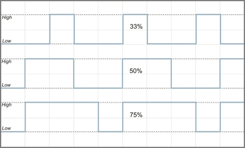
Digital to analog converter can be easily implemented with Pulse Width Modulation (PWM). On the following figure you can see three PWM signals with different duty cycles. The duty cycle describes the proportion of positive pulse width to the period. PWM waveforms with 33%, 50% and 75% of duty cycle are shown below. These three PWM signals can be converted to three different analog values, at 33%, 50%, and 75% of the full strength. For instance, when the voltage level is 5V and the duty cycle is 50%, digital to analog converter outputs 2.5V.
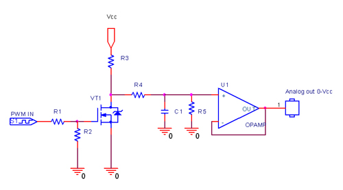
The simplest saving digital to analog converter circuit with high-resistance output is presented on the following schematics:

The next figure shows the digital to analog converter circuit with low-resistance output:

To get the DAC with the voltage range different from 5V, you can use the circuit from the following schematics: